RC-BX30
1-6
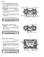
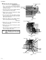
Fig.5
Fig.6
Fig.7
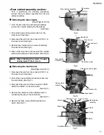
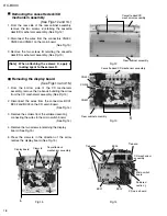
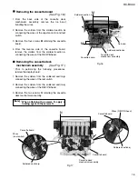
<Front cabinet assembly section>
Prior to performing the following procedures,
remove the front cabinet assembly from the rear
cabinet assembly.
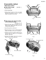
Removing the right and left speaker
assemblies
(See Fig. 5.)
1.
2.
3.
From the inside of the front cabinet assembly,
remove the six screws
B
retaining the right and left
speaker assemblies.
Remove the solders from the soldered sections
b
of the right and left speaker assemblies, remove
the speaker wires.
Take out the right and left speaker assemblies.
Removing the cassette door gear
assembly
(See Fig. 6.)
1.
2.
From the inside of the front cabinet assembly,
remove the two screws
C
retaining the cassette
door gear assembly.
Take out the cassette door gear assembly.
[Note]
When attaching the screws C, apply a
locking agent to the screws C.
[Note]
When attaching the screws B, apply a
locking agent to the screws B.
Removing the cassette door
(See Fig. 7.)
1.
2.
While pressing the section
c
of the cassette door in
the direction of the arrow, remove the boss
d
of the
cassette door from the section
e
of the front cabinet
assembly.
Disengage the boss
f
of the cassette door from the
section
g
of the front cabinet assembly.
Prior to performing the following procedures,
remove the cassette door gear assembly.
[Note]
Be sure to hang the spring to the
section h before attaching the cassette
door to the front cabinet assembly.
B
B
B
Front cabinet assembly
Cassette door gear assembly
Cassette door
Section
e
Section
c
Boss
d
Boss
f
Section
g
Section
h
Spring
Front cabinet assembly
Right speaker
assembly
Left speaker assembly
Soldered section
b
Soldered section
b
C
C
B
Speaker wires
Summary of Contents for RC-BX30
Page 23: ...RC BX30 1 23 M E M O ...

