RC-BX30
1-7
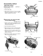
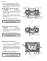
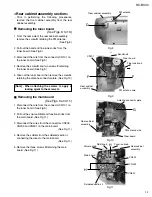
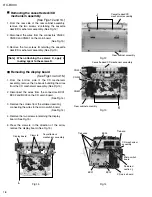
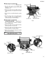
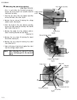
Fig.10
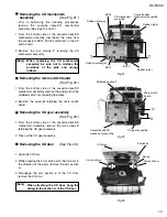
Fig.11
Fig.8
Fig.9
Removing the tuner board
(See Figs. 8 to 10.)
1.
2.
3.
4.
5.
From the rear side of the rear cabinet assembly,
remove the screw
D
retaining the FM antenna.
(See Fig.8.)
Pull out the band and fine tune knobs from the
tuner board. (See Fig.9.)
Disconnect the wire from the connector CN101 on
the tuner board. (See Fig.9.)
Remove the screw
E
and two screws
F
retaining
the tuner board. (See Fig.9.)
Take out the tuner board, then remove the screw
G
retaining the antenna connector plate. (See Fig.10.)
<Rear cabinet assembly section>
Prior to performing the following procedures,
remove the front cabinet assembly from the rear
cabinet assembly.
[Note]
When attaching the screws G, apply a
locking agent to the screws G.
Removing the main board
(See Figs. 9 and 11.)
1.
2.
3.
4.
5.
Disconnect the wire from the connector CN101 on
the tuner board. (See Fig.9.)
Pull out the volume, DBB and function knobs from
the main board. (See Fig.11.)
Disconnect the wires from the connectors CN302,
CN303 and CN501 on the main board.
(See Fig.11.)
Remove the solders from the soldered section
i
connecting the wires to the main board.
(See Fig.11.)
Remove the three screws
H
retaining the main
board. (See Fig.11.)
D
G
H
H
F
F
Rear cabinet assembly
Rear cabinet
assembly
Rear cabinet
assembly
Rear cabinet
assembly
Main board
Volume knob
DBB knob
CN302
CN303
CN501
Function knob
Soldered section
i
FM antenna
Tuner board
Tuner board
Antenna connector plate
Fine tune knob
Band knob
CN101
FM antenna wire
FM antenna wire
Summary of Contents for RC-BX30
Page 23: ...RC BX30 1 23 M E M O ...

