RC-BX30
1-11
Fig.21
Fig.23
Fig.22
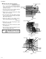
Removing the CD mechanism
assembly
(See Fig. 21.)
1.
2.
From the bottom side of the cassette deck/CD
mechanism assembly, disconnect the wires from
the connectors BC01, BC02 and BC03 on the CD
servo board.
Remove the four screws
T
retaining the CD
mechanism assembly.
Prior to performing the following procedures,
remove the cassette deck/CD mechanism
assembly. (See Figs.12 and 13.)
[Note]
When replacing the CD mechanism
assembly, be sure not to mistake the
positions of the pink and orange
rubbers.
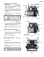
Removing the micro switch board
(See Fig. 22.)
1.
2.
From the bottom side of the cassette deck/CD
mechanism assembly, remove the solders from the
soldered section
t
connecting the wires.
Remove the screw
U
retaining the micro switch
board.
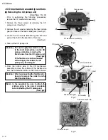
Removing the CD gear assembly
(See Fig. 23.)
1.
2.
From the bottom side of the cassette deck/CD
mechanism assembly, remove the two screws
V
retaining the CD gear assembly.
Take out the CD gear assembly.
Removing the CD door
(See Fig. 23.)
1.
2.
3.
Open the CD door.
While pressing the arm section
u
of the CD door in
the direction of the arrow, remove the arm section
u
.
Disengage the arm section
v
of the CD door,
remove the CD door.
[Note]
When attaching the CD door, hang the
spring to the section w of the CD door.
BC01
BC02
BC03
CD mechanism
assembly
Rubber (pink)
Rubber (pink)
Rubber (oranmge)
Cassette deck
mechanism assembly
Cassette deck/CD
mechanism assembly
Rubber (orange)
CD gear assembly
Soldered section
t
CD door
Arm section
v
Arm section
u
Section
w
Spring
Micro switch
board
T
T
V
U
Summary of Contents for RC-BX30
Page 23: ...RC BX30 1 23 M E M O ...

