- 36 -
Auto Position
If you shift the picture horizontally or vertically
to an unwanted position, use this item to put
the picture into correct place automatically.
Select Auto position item by using or
buttons.
Press
OK
button.
Press
MENU
button or
BACK
button to
store the value.
Warning:
Auto position adjustment recom-
mended to be done with the full screen im-
age for the proper adjustment.
Horizontal Position
This item shifts the image horizontally to
right hand side or left hand side of the
screen.
Select
Hor. Position
item by using or
button.
Use or button to adjust the value.
Press
MENU
button or
BACK
button to
store the value.
Vertical Position
This item shifts the image vertically towards
the top or bottom of the screen.
Select
Ver. Position
item by using or
button.
Use or button to adjust the value.
Press
MENU
button or
BACK
button to
store the value.
Dot Clock
Dot Clock adjustments correct interference
that appear as vertical banding in dot inten-
sive presentations like spreadsheets or
paragraphs or text in smaller fonts.
Use or button to adjust the value.
Clock Phase
Depending on the resolution and scan fre-
quency that you input to the TV Set, you may
see a muddy or noisy picture on the screen.
In such a case you can use this item to get a
clear picture by trial and error method.
Use or button to adjust the value.
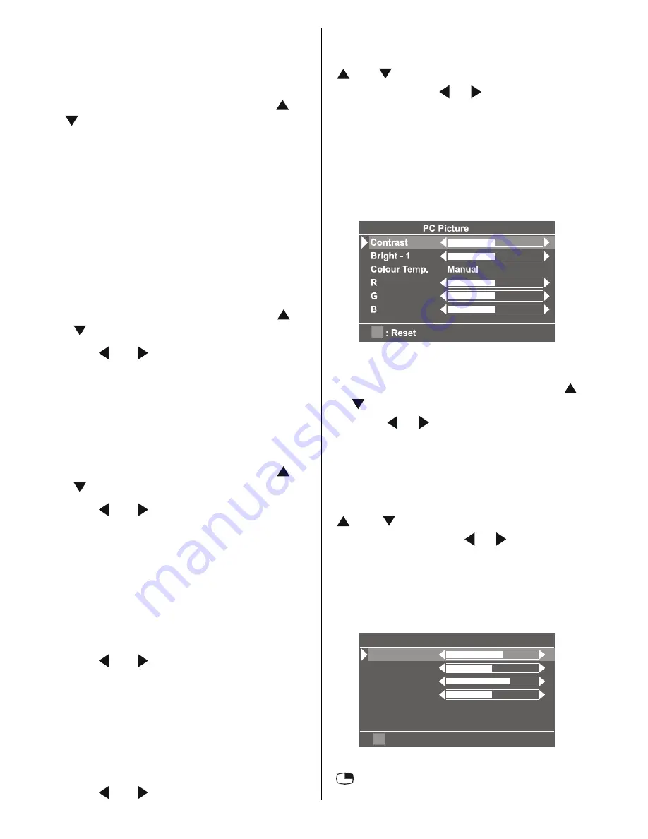
PC Picture Menu
In the Main menu, select
PC Picture
using
or button, then enter the PC Picture
menu by pressing / or
OK
buttons.
Contrast, Bright-1 and Colour Temperature
adjustments in this menu are identical to
adjustments defined in TV picture menu.
R, G, and B adjust the TV image colour in
PC mode. You can change the TV colour to
your desired colour: R (Red), G (Green), B
(Blue)
Sound Menu
In the main menu select
Sound
using
or button then enter the Sound menu by
pressing / or
OK
buttons.
The items in this menu are described at
Sound menu starting
page 29
.
PIP Picture
In the Main menu, select
PIP Picture
using
or button, then enter the PIP Pic-
ture menu by pressing / or
OK
but-
tons.
This menu is displayed when PIP is dis-
played on the screen. Otherwise PIP No
Signal message will be displayed at the
bottom of menu.
3,33LFWXUH
&RQWUDVW
%ULJKW
&RORXU
6KDUSQHVV
5(6(7
3,36L]H
3,33RVLWLRQ
PIP picture is displayed on the screen by
button.
ENG-20710W-17MB16P-1895UK-(LT-20DA6SK)-50076128.p65
18.10.2005, 08:39
36
Summary of Contents for LT-20DA6SK
Page 22: ...2 12 No YA354 No YA354 2 11 MAIN PWB ASS Y 3 12 VE 20228287 MAIN PWB CIRCUIT DIAGRAM 3 12 ...
Page 23: ... No YA354 2 13 2 14 No YA354 MAIN PWB ASS Y 4 12 VE 20228287 MAIN PWB CIRCUIT DIAGRAM 4 12 ...
Page 24: ...2 16 No YA354 No YA354 2 15 MAIN PWB ASS Y 5 12 VE 20228287 MAIN PWB CIRCUIT DIAGRAM 5 12 ...
Page 25: ... No YA354 2 17 2 18 No YA354 MAIN PWB ASS Y 6 12 VE 20228287 MAIN PWB CIRCUIT DIAGRAM 6 12 ...
Page 26: ...2 20 No YA354 No YA354 2 19 MAIN PWB ASS Y 7 12 VE 20228287 MAIN PWB CIRCUIT DIAGRAM 7 12 ...
Page 27: ... No YA354 2 21 2 22 No YA354 MAIN PWB ASS Y 8 12 VE 20228287 MAIN PWB CIRCUIT DIAGRAM 8 12 ...
Page 28: ...2 24 No YA354 No YA354 2 23 MAIN PWB ASS Y 9 12 VE 20228287 MAIN PWB CIRCUIT DIAGRAM 9 12 ...
Page 29: ... No YA354 2 25 2 26 No YA354 MAIN PWB ASS Y 10 12 VE 20228287 MAIN PWB CIRCUIT DIAGRAM 10 12 ...
Page 30: ...2 28 No YA354 No YA354 2 27 MAIN PWB ASS Y 11 12 VE 20228287 MAIN PWB CIRCUIT DIAGRAM 11 12 ...
Page 31: ... No YA354 2 29 2 30 No YA354 MAIN PWB ASS Y 12 12 VE 20228287 MAIN PWB CIRCUIT DIAGRAM 12 12 ...
Page 33: ... No YA354 2 33 2 34 No YA354 TOP PATTERN DIAGRAMS MAIN PWB PATTERN SOLDER SIDE ...
Page 34: ...2 36 No YA354 No YA354 2 35 TOP MAIN PWB PATTERN PARTS SIDE ...
Page 83: ... 2005 Victor Company of Japan Limited 0205MKH VT VT 50076128 ...


