1-16 (No.YF034)
•
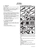
Guide driver (Hexagonal)
To be used to turn the guide roller to adjustment of the linarity
of playback envelope.
•
INF adjustment lens
To be used for adjustment of the camera system. For the
usage of the INF adjustment lens, refer to the Service Bulletin
No. YA-SB-10035.
•
INF lens holder
To be used together with the Camera stand for operating the
Videocamera in the stripped-down condition such as the sta-
tus without the exterior parts or for using commodities that are
not yet conformable to the interchangeable ring. For the usage
of the INF lens holder, refer to the Service Bulletin No. YA-SB-
10035.
•
Camera stand
To be used together with the INF adjustment lens holder. For
the usage of the Camera stand, refer to the Service Bulletin
No. YA-SB-10035.
•
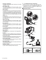
Light box assembly
To be used for adjustment of the camera system. For the
usage of the Light box assembly, refer to the Service Bulletin
No. YA-SB-10035.
•
Gray scale chart
To be used for adjustment of the camera system. For the
usage of the INF adjustment lens, refer to the Service Bulletin
No. YA-SB-10035.
•
Color bar chart
To be used for adjustment of the camera system. For the
usage of the INF adjustment lens, refer to the Service Bulletin
No. YA-SB-10035.
•
Alignment tape
To be used for check and adjustment of interchangeability of
the mechanism.
•
PC cable
To be used to connect the Videocamera and a personal computer
with each other when a personal computer issued for adjustment.
•
Communication cable
Connect the Communication cable between the PC cable and
Jig connector cable when performing a PC adjustment.
•
Service support system
To be used for adjustment with a personal computer. Software
can be downloaded also from JS-net.
•
Jig connector cable
Connected to JIG CONNECTOR of the main board and used
for electrical adjustment, etc.
•
Extension connector
Connect this extension connector to the connector of the Jig
connector cable for extending the cable connector.
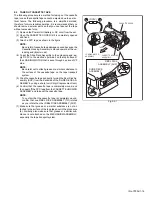
4.2
JIG CONNECTOR CABLE CONNECTION
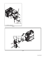
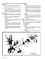
• Remove one screw (1), and remove the COVER (JIG CON).
• As the figure shows, insert JIG CONNECTOR CABLE in JIG
CONNECTOR by using the EXTENSION CONNECTOR so
that the wire side faces downward.
Connection procedure
PC CABLE
FOR
COMMUNICATION CABLE
COMMUNICATION CABLE
JIG CONNECTOR CABLE
EXTENSION CONNECTOR
SCREW(1)
COVER(JIG CON)
SCREW(2)
COVER(ADJ)
TO JLIP_RX
TO JLIP_TX
TO GND
TO ENV_OUT
TO HID1
MENU
RS232C
COM PORT
SERVICE SUPPORT SYSTEM
COMMUNICATION CABLE
JIG CONNECTOR
OSCILLOSCOPE
JIG CONNECTOR
PERSONAL COMPUTER
RED
WHITE
BLACK
GUIDE ROLLER (TU)
GUIDE ROLLER (SUP)

