(No.YF034)1-13
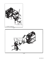
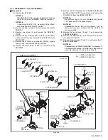
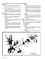
3.2.4 DISASSMBLY of [12] VF ASSEMBLY
z
Disassembly
(1) Remove the EYE CUP.
NOTE12a:
After the EYE CUP is removed, be careful of handling
the EYE CUP since the SHEET (LENS) is removed.
NOTE12b:
In attaching the EYE CUP, be careful of the attach-
ment direction of the SHEET (LENS).
(2) Remove the three screws (1-3) and remove the HOLD-
ER (EYE).
(3) Remove one screw (4) and remove the BRACKET
(TOP2).
(4) Remove the two screws (5 and 6), lift the VF COVER in
a direction of arrow, and remove the VF COVER from the
ZOOM UNIT.
(5) Remove the FPC from one connector (CN12a), remove
one screw (7), and remove the ZOOM UNIT.
(6) Remove the two screws (8 and 9), and remove the
BRACKET.
(7) Remove the FPC attached to the GUIDE (OUTER) little
by little so that the FPC moves easily, and remove the
COVER (VF) from the GUIDE (OUTER).
NOTE12c:
Be careful enough not to cut or damage the removed
FPC since the FPC is attached again.
NOTE12d:
Disassemble the COVER (VF) if necessary. In an at-
tachment procedure, confirm that the LEVER (1)
moves smoothly.
(8) Remove the two screws (10 and 11), and remove the
FRAME ASSEMBLY.
(9) Remove the SPACER (A), and remove the FPC from
one connector (CN12b).
(10) Remove the two screws (12 and 13), and remove the VF
BOARD ASSEMBLY.
NOTE12e:
Disassemble the FRAME ASSEMBLY if necessary. In
an assembly procedure, be careful not to insert foreign
materials inside the VF and not to soil the VF.
Fig.3-2-4
a
a
c
e
c
d
d
e
F1
F1
VF BOARD
ASSEMBLY
[0][6]
f
g
g
f
CASE(B.LIGHT)
SHEET(DIFF)
GUIDE(LCD)
SHEET(POLA)
HOLDER(SHEET)
< FRAME ASSEMBLY >
< CASE(VF) >
SPRING(LCD)
SHEET(POLA)
LCD MODULE
FRAME(VF)
STOPPER(POLA)
LENS HOLDER
ASSEMBLY
LEVER(1)
LEVER(2)
14
(S12e)
BRACKET
BRACKET(TOP2)
4
(S12b)
11
(S12d)
9
(S12b)
8
(S12b)
10
(S12d)
CN12b
12
13
(S12d)
(S12d)
SPACER(A)
CN12a
FPC
7
(S12c)
6
(S12c)
5
(S12a)
1
(S12c)
2
(S12a)
3
(S12a)
CASE(VF)
GUIDE(OUTER)
HOLDER(EYE)
EYE CUP
ZOOM UNIT
VF COVER
SHEET(LENS)
NOTE12e
NOTE12d
NOTE12c
NOTE12a,b
: 0.059N
.
m(0.6kgf
.
cm)
: 0.049N
.
m(0.5kgf
.
cm)


