


1.
DESCRIPTION
1.1
FUNCTIONAL DESCRIPTION
This document describes the operation and installation of
the DV-180 Digital Controller. The DV-180
is designed to meet the demanding challenges of remote motion and camera control for the JVC GY-
DV300U camera. It has been specifically configured to control up to four DV-115 Digital Pan & Tilt Heads.
The DV-180 Digital Controller is designed for long distance remote control requirements in
applications such as worship services, teleconferencing, university distance learning, tele-medicine
and theater or auditorium presentations
The DV-180 has a suite of features which enhance the video presentation. Among the features is a
professional preset capability. Presets allow a predetermined pan, tilt, zoom and focus position to
be stored in the DV-115 non-volatile memory. This stored position information may later recalled
for accurately repeating the previously stored shot. With the resolution of the pan & tilt presets
being 12 bits, the preset repeatability is 0.1 degrees in both pan & tilt. The preset data is stored
within the pan and tilt head.
Eight presets per camera site
may be programmed from the DV-180.
The pan and tilt control is provided by a proportional deflection joystick. Control of the zoom and focus is
accomplished with proportional deflection “Seesaw” controls. The proportional controls allow a slow
movement when the control is only slightly depressed increasing to a faster response when the control is
fully depressed.
In addition to basic pan, tilt, zoom and focus control, the DV-180 allows control of
iris (automatic or manual), video tape recording controls, camera/bars selection, automatic or
manual focus selection and, of course, presets.
The versatile digital interface of the DV-180 Controller will also communicate with the user’s computer
system. Camera, tape, and pan and tilt commands may be routed to all the cameras on the system through the
DV-180 to Computer interface.
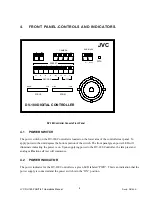
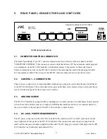
1.2 PHYSICAL
DESCRIPTION
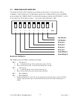
The DV-180 Controller tabletop version features a sloped front panel for ready access to all of the DV-180
Controller controls. Four RS-422 connectors are located on the rear of the unit to interface to each of the 4
remote camera sites. A 15 Pin D female connector is located on the rear of the DV-180. This connector
provides the interface to the user’s computer system for Camera Control functions. A computer program is
supplied with the DV-180 which provides Gain, Shutter and White Balance control of the GY-DV300.
Input power to the DV-180 Controller is provided by a wall mounted power supply which is provided with
the unit.
JVC DV-180 PAN/TILT Operations Manual
Doc #: D0154-A
4