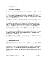


7.13 COLOR BAR GENERATION
An industry standard color bar pattern can be generated from the GY-DV300U camera. To activate this
control, verify the PAGE LED is illuminated indicating the functions listed under the AUILLARY 2 switch
is enabled, and then depress AUILLARY 2 switch, color bars will be displayed on monitor. To disable the
bars depress the switch again.
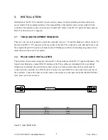
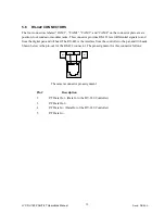
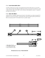
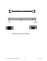
7.14 CABLE
DRAWINGS
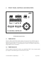
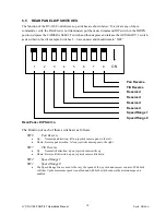
Attached are the two applicable cable drawings for the DV-180 Controller, these include; drawing 960379
the RS-422 I/F cable between the DV-180 Controller and the pan and tilt heads and drawing 2030066, the
RS-232 cable between the DV-180 Controller the user’s personal computer.
1
3
2X
Pin 1
2
Blk
Red
Grn
Yel
.25 In.
ACA96037900
1. Strip jacket .375 Inches.
2. Fan and flatten to color pattern.
3. Trim straight to .250 Inches.
4. Insert in connector and crimp
Black
Red
Green
Yellow
P/T Tx -
P/T Tx +
P/T Rx -
P/T Rx +
2
3
4
5
2
3
4
5
6 Inches.
RS-422 I
NTERFACE
C
ABLE
, P/N ACA96037900
JVC DV-180 PAN/TILT Operations Manual
Doc #: D0154-A
18