


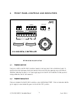

5.
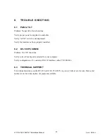
REAR PANEL-CONNECTORS AND SWITCHES
COMPUTER
CONTROL
POWER
+12 VDC
+
-
CAM1
CAM2
CAM3
CAM4
SETUP
Made in USA
www.jvc.com
S/N:
ON
1 2 3 4 5 6 7 8
Camera Controller for GY-DV300U
JVC
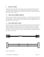
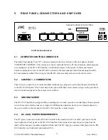
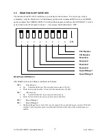
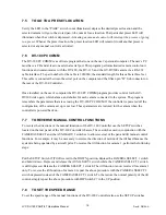
DV-180 Controller Rear Panel
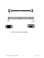
5.1
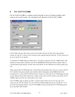
COMPUTER CONTROL CONNECTOR
The female high density15 pin “D” connector located in the lower left area of the rear panel is labeled
“COMPUTER CONTROL”. This connector accepts a cable that allows a PC based camera control program
to communicate via the DV-180 Controller to individual cameras in the system. In this mode Camera
Control commands are sent via the DV-180 Controller to the individual pan and tilt heads using their RS-
422 communication links. The wiring for this RS-422 cable assembly is shown in the cable section.
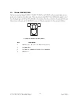
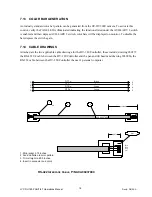
5.2
CAMERA 1 - 4 CONNECTORS
These four, six conductor, four contact modular telephone type plugs are used to link the pan and tilt heads
to the DV-180 Controller. The control data for the pan and tilt head or the camera will go out the port that is
selected on the front panel by the camera select switches.
5.3
GROUND SCREW
The DV-180 Controller is equipped with a grounding screw to make provision for attaching a chassis ground
wire to the metal controller console. A single 4-40 Phillips head stainless steel screw is located adjacent to
the power switch on the rear panel of the DV-180 Controller console chassis.
5.4
DC JACK, POWER REQUIREMENTS
The DC power connection for the DV-180 Controller is the small circular 5.5 mm DC jack located on the
lower right area of rear panel on the DV-180 Controller. This connector accepts the power plug from the
small wall mount power modules supplied with the unit. The DC plug type connector that plugs into the DV-
180 Controller is a Switchcraft part number S760.
JVC DV-180 PAN/TILT Operations Manual
Doc #: D0154-A
11