


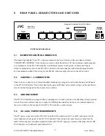

5.6 RS-422
CONNECTORS
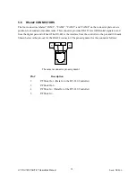
The four connectors labeled “CAM1”, “CAM2”, “CAM3”, and “CAM4” on the connector plate are six
position, four conductor modular jacks. This connector provides RS-422 level differential signals to and
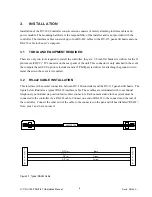
from the digital pan and tilt head. The RS-422 is the interface from the controller to the pan and tilt heads.
Shown below is the pin-out for the RS-422 connector. The pin assignment for this connector follows:
Pin 2
Pin 5
Pin 6
Not
Used
Pin 1
Not
Used
The camera connector pin assignment:
Pin #
Description
2
P/T Data Out - (Data In to the DV-180 Controller)
3
P/T Data Out +
4
P/T Data In - (Data Out of the DV-180 Controller)
5
P/T Data In +
JVC DV-180 PAN/TILT Operations Manual
Doc #: D0154-A
13