background image

2

Safety Precautions

WARNING:

 TO REDUCE RISK OF FIRE OR ELECTRIC SHOCK, 

DO NOT EXPOSE THIS APPARATUS TO RAIN OR 
MOISTURE. NO OBJECTS FILLED WITH LIQUIDS, SUCH 
AS VASES, SHALL BE PLACED ON THE APPARATUS.

IMPORTANT SAFEGUARDS

Electrical energy can perform many useful functions. This unit has 
been engineered and manufactured to assure your personal safety. 
But 

IMPROPER USE CAN RESULT IN POTENTIAL ELECTRIC 

SHOCK OR FIRE.

 In order not to defeat the safeguards incorporated 

into this product, observe the following basic rules for its installation, 
use, and service. Please read these “IMPORTANT SAFEGUARDS” 
carefully before use.

All the safety and operating instructions should be read before the 

• 

product is operated.
The safety and operating instructions should be retained for future 

• 

reference.
All warnings on the product and in the operating instructions should 

• 

be adhered to.
All operating instructions should be followed.

• 

POWER CONNECTION

The power supply voltage rating of this product is AC 120 V 
(For U.S.A. and Canada) and AC 220 – 240 V (For European 
countries, Asian countries, and United Kingdom).
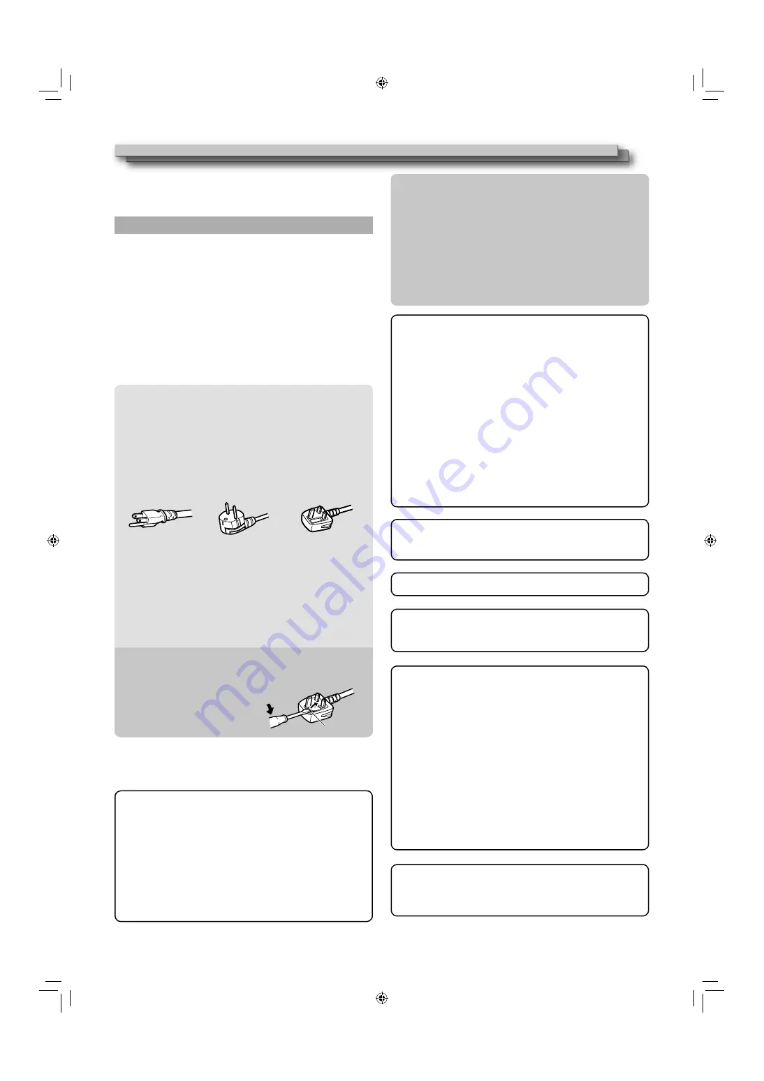
The power cord attached conforms to the following power supply 
voltage and countries. Use only the power cord designated to 
ensure safety and EMC regulations of each country.

Not all types of power cords are supplied to this product.

• 

For U.S.A. and 
Canada: AC 120 V

For European and 
Asian countries: 
AC 220 – 240 V

For United Kingdom: 
AC 220 – 240 V

This plug will fit only into a grounded power outlet. If you are 
unable to insert the plug into the outlet, contact your electrician to 
install the proper outlet. Do not defeat the safety purpose of the 
grounded plug.

This product should be operated only with the type of power 

• 

source indicated on the label. If you are not sure of the type of 
power supply of your home, consult your product dealer or local 
electric power company.

Warning:

Do not use the same power cord for AC 120 V as for AC 220 – 

• 

240 V. Doing so may cause malfunction, electric shock or fire.

Under the following conditions,
1.  Turn off the power.
2.  Unplug this product from the wall outlet.
3.  Refer service to qualified service personnel.

a)  When the product emits smoke or unusual smell.
b)  When the product exhibits a distinct change in performance

 —for example, no picture or no sound.

c)  If liquid has been spilled, or objects have fallen on the product.
d)  If the product has been exposed to rain or water.
e)  If the product has been dropped or damaged in any way.
f)  When the power supply cord or plug is damaged.

Do not install this product in the following places:

• 

in a damp or dusty room


where the product is exposed to soot or steam, such as 


near the cooking counter or a humidifier 

near heat sources


where condensation easily occurs, such as near the window


in a location exposed to direct sunlight or strong light


Do not place this product on an unstable cart, stand, or table. 

• 

The product may fall, causing serious injury to a child or adult, 
and serious damage to the product.
The product should be mounted according to the 
manufacturer’s instructions, and should use a mount 
recommended by the manufacturer.

Do not use this product near water.

• 

Be sure to install the product in the place where proper 

• 

temperature and humidity are kept (

 “Operation environment” 

on page 32).
This product becomes hot during its use. Take enough care 
when handling the product.

Do not attempt to service this product yourself, as opening or 
removing covers may expose you to dangerous voltages and 
other hazards. Refer all service to qualified service personnel.

Do not use the product for a long time if the sound is distorted.

The AC power supply is controlled by turning on/off the 

• 

POWER switch on the rear panel. If the product is installed in a 
place where you cannot easily turn on/off the POWER switch, 
control the AC power supply by plugging/unplugging the power 
cord into/from the AC outlet. In this case, install the product as 
close to the AC outlet as possible, and leave enough space for 
plugging/unplugging the power cord. If the product is installed 
in a place where you cannot easily plug/unplug the power cord, 
equip an easily accessible device to the wiring of the building 
for turning on/off the power.

When the product is left unattended and unused for a long 

• 

period of time, unplug it from the wall outlet and disconnect the 
cable system.

Do not overload wall outlets, extension cords, or convenience 

• 

receptacles on other equipment as this can result in a risk of 
fire or electric shock.

Use only the accessory cord designed for this product to 

• 

prevent shock.

The Mains Plug is used as the disconnect device, the disconnect 
device shall remain readily operable.
To completely disconnect this apparatus from the AC mains, 
disconnect the power supply cord plug from the AC receptacle.

Note for United Kingdom power cord only

The plug of United Kingdom power cord has a built-in fuse. When 
replacing the fuse, be sure to use only a correctly rated approved type, 
re-fit the fuse cover. (Consult your dealer or qualified personnel.)

How to replace the fuse

Open the fuse compartment with the 
blade screwdriver, and replace the 
fuse.

Fuse

Warning:

  This is a class A product. In a domestic environment this 

product may cause radio interference in which case the 
user may be required to take adequate measures.

Before connecting other products such as VCR’s and personal 

• 

computers, you should turn off the power of this product for 
protection against electric shock.

Do not use attachments not recommended by the manufacturer 

• 

as they may be hazardous.

When replacement parts are required,

• 

 be sure the service 

technician has used replacement parts specified by the 
manufacturer or equivalents. Unauthorized substitutions may 
result in fire, electric shock, or other hazards.

Upon completion of any service or repairs to this product,

•  

ask the service technician to perform safety checks to 
determine that the product is in proper operating condition.

Use only the power source specified on the unit.

AC power: 120 V/220 – 240 V, 50 Hz/60 Hz

• 

DC power: 24 V

• 

DT3D24G1̲EN.indb   2

DT3D24G1̲EN.indb   2

11.1.25   0:53:41 PM

11.1.25   0:53:41 PM

Summary of Contents for DT-3D24G1

Page 1: ... ELECTRICAL SHOCK DO NOT OPEN The lightning flash with arrowhead symbol within an equilateral triangle is intended to alert the user to the presence of uninsulated dangerous voltage within the product s enclosure that may be of sufficient magnitude to constitute a risk of electric shock to persons The exclamation point within an equilateral triangle is intended to alert the user to the presence of...

Page 2: ...ious damage to the product The product should be mounted according to the manufacturer s instructions and should use a mount recommended by the manufacturer Do not use this product near water Be sure to install the product in the place where proper temperature and humidity are kept Operation environment on page 32 This product becomes hot during its use Take enough care when handling the product D...

Page 3: ...eiae org WARNING TO PREVENT FIRE OR SHOCK HAZARDS DO NOT EXPOSE THIS APPARATUS TO RAIN OR MOISTURE WARNING THIS APPARATUS MUST BE CONNECTED TO A MAINS SOCKET OUTLET WITH A PROTECTIVE EARTHING CONNECTION CAUTION DANGER OF EXPLOSION IF BATTERY IS INCORRECTLY REPLACED REPLACE ONLY WITH THE SAME OR EQUIVALENT TYPE IMPORTANT SAFETY INSTRUCTIONS 1 Read these instructions 2 Keep these instructions 3 Heed...

Page 4: ... are near the audio cable or the signal cable the sound or the picture will contain noise In such cases please keep the cable away from the sources of the disturbance Attention This symbol is only valid in the European Union Caution for use of the product for many hours In the case that you use the monitor for many hours we recommend that you set NO SYNC ACTION in SYNC FUNCTION to P SAVE in MAIN M...

Page 5: ... rig to 3D images Various functions useful on the spot CAMERA ASSIST MENU 7 menus useful in various shooting scenes 3D cursor Cursor mode for displaying the visual difference between left and right eyes in pixels percentage Grid mode for checking the visual difference by grid lines Viewing 3D images 12 Basic 3D principle 12 Compatible 3D format 12 When viewing in 3D 12 To view 3D images 13 To view...

Page 6: ...nd plate is attached to the lower position of the stand body Do not rest your arm on the monitor or lean against the monitor Do not touch the LCD panel when installing the monitor Be sure to install the monitor securely to prevent the monitor from falling over which may cause damage to the monitor or injury Screw silver Approx 148 To detach the stand Lay the monitor on a cloth with the LCD panel f...

Page 7: ...n analog signal then emitted is emitted only when SDI 1 L or SDI 2 R is selected and when EMBEDDED AUDIO signals come in to the E AUDIO 3G SDI HD SDI SD SDI IN 1 L or IN 2 R terminal 8 E AUDIO 3G SDI HD SDI SD SDI IN 1 L IN 2 R terminals BNC Input terminals for the 3G SDI HD SDI SD SDI signals The terminals accept also EMBEDDED AUDIO signals including up to 12 audio channels with a sampling freque...

Page 8: ...L page 15 PUSH SEL button Switches the display line Used for the following functions 3D cursor page 16 SPLIT page 15 To reset the displayed line and R image to default press and hold the PUSH SEL button for 3 seconds or longer Daily Operations Tally lamp This lamp is controlled by the tally function of the MAKE TRIGGER terminal You can select the color of the tally lamp from GREEN or RED TALLY SEL...

Page 9: ...s in the following order When the MIX mode is OFF or invalid Wave form monitor Vectorscope No display When the MIX mode is ON page 16 No display Parallel wave form monitor Parallel vector scope Difference wave form monitor Difference vector scope r T C time code button lamp Activates deactivates the display of the time data time code contained in the SDI signal On the Information Display on page 1...

Page 10: ...ure is displayed without overlapping the information display area However the information display will overlap with the picture when Displaying the picture with higher resolution than the resolution of the panel in 1 1 mode SD4 3 LARGE in the FUNCTION SETTING of SET UP MENU is set to ON page 23 1 Audio level meter You can check the conditions of the EMBEDDED AUDIO signals when LEVEL METER ch is se...

Page 11: ...L LINK appears when the MAIN MENU SDI DUAL LINK page 19 is set to ON in SDI input and the 3G SDI signal information appears when the MAIN MENU SDI DUAL LINK is set to OFF However in MIX mode the 3G SDI signal information appears even when the MAIN MENU SDI DUAL LINK is set to ON Status indication of 3G SDI signal information Following signal information can be displayed when a 3G SDI signal comes ...

Page 12: ... RealD Inc US When viewing in 3D View 3D images at the recommended viewing distance Recommended viewing distance Approx 65cm 25 5 8 To view in 3D change to a suitable mode before putting on the circular polarizing glasses to view the 3D images Every individual will have a different experience when viewing 3D images Viewing at a close distance may cause disorders and discomfort The 3D effects may d...

Page 13: ... in a signal format that scales the screen vertically use the 1 1 display mode To view images taken by two cameras Mix L and R images taken by two cameras and convert them to 3D images 1 Input L images into the SDI IN 1 L terminal and R images into the SDI IN 2 R terminal Input L and R images in the same format corresponding to the MIX mode For 3G SDI LEVEL B Dual Stream input into the SDI IN 1 L ...

Page 14: ... 180 degree rotation settings of an image The settings are retained even when the CAMERA ASSIST MENU closes Half mirror Half mirror Parallel twin flex Setting value Content OFF Does not rotate or flip the image R H MIRROR Horizontally flips images input into the SDI IN 2 R terminal R V MIRROR 1 Vertically flips images input into the SDI IN 2 R terminal L H MIRROR Horizontally flips images input in...

Page 15: ...s between L and R images L image Upper left R image Upper right LR SWAP L and R images are exchanged and then displayed You can exchange the images without repluging the terminals The setting is retained even when the menu closes Note that L and R images have been exchanged when the setting is set to ON L image R image SDI IN SDI IN 1 L 2 R SDI IN SDI IN 1 L 2 R LR SWAP OFF LR SWAP ON L and R imag...

Page 16: ...splayed in R SHIFT or ANAGLYPH of the CAMERA ASSIST MENU The vector scope is not displayed when the input signals are RGB When 3D is ON the L and R lines measuring the visual difference between L and R images and the pixels and percentage between the lines are displayed The following two modes are available for the line display Cursor mode and Grid mode Each time you press the 3D CURSOR button the...

Page 17: ... be moved separately Pressing and holding the PUSH SEL button for 3 seconds or longer resets the displayed lines to the default positions Grid mode The grid lines appear which measure the visual difference The following two types of the grid mode display are available Normal display and Center window display You can change the display by pressing the SELECT button Normal display Center window disp...

Page 18: ...LAY TIME LOW LATENCY ASPECT 3G SDI LEVEL B SDI DUAL LINK 3D SETTING SCOPE SETTING E AUDIO GROUP LEVEL METER SETTING LEVEL METER ch BAR TYPE REFERENCE LEVEL OVER LEVEL BAR BRIGHTNESS PEAK HOLD FUNCTION SETTING sub menu POSI PICTURE SUB ADJ CONTRAST TALLY SELECT BRIGHT SD4 3 LARGE H POSITION ADJ 3D H POSITION CHROMA DIMMER sub menu WHITE BALANCE SET reset sub menu REMOTE SETTING reset INFORMATION CO...

Page 19: ...L image SIDE BY SIDE compressed horizontally L image on the left SIDE BY SIDE compressed horizontally R image on the left SIDE BY SIDE not compressed L image on the left SIDE BY SIDE not compressed R image on the left When the 3D mode is ON in 3D input pressing the SELECT button switches between FORMAT1 and FORMAT2 SDI FORMAT 2 1 Set the second choice for 3D format in SDI input DVI FORMAT 1 1 Set ...

Page 20: ...marker 80 100 FRAME Displays hides the frame indicating the area of the specified aspect ratio OFF ON CENTER MARKER Displays hides the marker indicating the center position of the picture OFF ON LINE BRIGHTNESS Adjust the brightness of the marker HIGH LOW 2 2 R AREA MARKER 3 Display Hide the area marker and select a type 4 OFF LINE HALF HALF L BLK BLK L R MARKER ASPECT 3 Select the aspect ratio of...

Page 21: ... and in gray for W 100 You can select the position of the level meter display top or bottom of the screen POSITION in INFORMATION on page 24 When PEAK HOLD is set to ON the maximum level meter value will remain displayed for a set period of time LEVEL METER ch Select how the audio channels are displayed on the level meter OFF LINE DIVIDE LINE DIVIDE Displays the channels 1 6 at the left of the scr...

Page 22: ...nitor is not displayed when the input signals are DVI input from a computer The vector scope is not displayed when the input signals are RGB 2 When SIZE is set to LARGE the window is displayed in the center of the screen regardless of the POSITION setting 3 Not displayed in MIX mode or when the CAMERA ASSIST button is ON SYNC FUNCTION Settings for the synchronization with signals Item Content Sett...

Page 23: ...isplay the sub menu which enables you to adjust the items in PICTURE SUB ADJ while viewing the actual picture reset Restore the default settings for all the items in PICTURE SUB ADJ You cannot select items to reset 1 Memorized for each input H POSITION ADJ Adjust the center position of SIDE BY SIDE images Item Content Setting value 3D H POSITION Display the center line to adjust the horizontal ima...

Page 24: ...ame to each video source as you like 10 characters at maximum You can also enter a name using the RS 232C system Setting of CHARACTER SET 1 Change the input to one that you want to assign a video source name for 2 Select CHARACTER SET 3 Press the buttons to select a character to enter at first Each time you press the button the characters change in the following order Press button to reverse the o...

Page 25: ...select AUTO Select COMPO RGB or PC when the picture is not displayed correctly with AUTO DVI D input of the monitor is compatible with HDCP SDI FORMAT Setting value AUTO MS1YCbCr MS2YCbCr MS3YCbCr MS4YCbCr MS2 RGB MS3 RGB 3G B DS Settings for formats of signals for 3G SDI HD SDI DUAL LINK input Automatically distinguishes signals when set to AUTO Normally select AUTO If the picture is unstable wit...

Page 26: ...ially available Consult your dealer if you need it Serial communication PC etc RS 485 IN RS 485 IN or RS 232C RS 485 OUT RS 485 IN RS 485 OUT RS 485 OUT For the details see page 28 Using the MAKE TRIGGER system The MAKE TRIGGER terminal is configured as follows You can assign a function to each pin terminal in REMOTE SETTING PIN1 PIN2 PIN3 PIN4 PIN5 in PARALLEL TYPE on page 24 You cannot change th...

Page 27: ... only at the moment of short circuiting 6 While controlling with the MAKE system the level meter is switched between displayed short circuiting and hidden opening When LEVEL METER ch is set to OFF the level meter is not displayed NO EFFECT appears While controlling with the TRIGGER system the pattern of the audio channel display is switched 7 While controlling with the MAKE system the available se...

Page 28: ...tions of the RS 232C terminal Pin No Signal 1 NC 2 RXD 3 TXD 4 NC 5 GND This is a female terminal 6 NC 7 RTS 8 CTS 9 NC The 7th terminal and the 8th terminal are connected Command outline All commands consist of the following segments Header Monitor ID Command ID Function Data Cr 0Dh On Header Operation commands from the personal computer etc Basic command list on page 29 Reference commands from t...

Page 29: ...r Displays the status 3 No data 19 1 B A M U T E x x 2 Cr Turns muting on off 00 Off 01 On 20 1 B A S P x x 2 Cr Changes the aspect ratio 00 4 3 01 16 9 21 1 B R O P O S I x x x x 2 Cr Configures POSITION settings 999 999 22 1 B R O P U S H x x 2 Cr Configures PUSH SEL settings 00 Change selection 01 Reset the position 23 1 B S E L E C T Cr Operates the SELECT keys No data 24 1 B 3 D S C A L E x x...

Page 30: ...s problem Check whether the setting of 1 1 is appropriate Check ASPECT of the MAIN MENU and SD4 3 LARGE under the SET UP MENU FUNCTION SETTING Check whether the input signal format is acceptable on the monitor 9 20 23 33 34 Some items do not appear on the menu The items which are not available for the current input or the current input signal are not displayed on the menu Change the input or the i...

Page 31: ... which lamps are flashing 2 Press button to turn off on standby the monitor 3 Turn off the AC power switch on the rear panel 4 Disconnect the AC power cord from the AC outlet 5 Contact your dealer with the information about which lamps were flashed If you turn on the monitor soon after turning it off or after a short term power failure the INPUT SELECT lamps may flash and no image may be displayed...

Page 32: ...r cord Power cord holder 1 Screw 2 for power cord holder Circular polarizing glasses 2 for 3D viewing not under warranty LCD panel Type 24 wide active matrix TFT Effective screen size Width 518 4 mm 20 1 2 Height 324 mm 12 7 8 Diagonal 611 3 mm 24 1 4 Number of pixels displayed 1920 1200 Number of colors displayed 16 77 million Contrast ratio TYP 1000 1 Input output terminals Video DVI D HDCP DVI ...

Page 33: ...080 29 97psF 1080 29 97psf 3 3 3 3 32 1080 24psF 1080 24psf 33 1080 23 98psF 1080 23 98psf 34 1080 25psF 1080 25psf 4 4 4 4 1 Compatible with EMBEDDED AUDIO signals 2 If there is no payload ID the signal is regarded as 1080 60i and 1080 60i and the status appear 3 If there is no payload ID the signal is regarded as 1080 59 94i and 1080 59 94i and the status appear 4 If there is no payload ID the s...

Page 34: ...rlace 14 1080 50p 1920 1080 56 25 50 0 Non interlace Non preset signals may not be displayed normally When a preset signal comes in the signal format is shown on the status display For other signals the resolution is shown Specification of the DVI D HDCP terminal Connect it to the DVI D output terminal on a personal computer Pin No Input signal 1 T M D S Data 2 2 T M D S Data 2 3 T M D S Data 2 sh...

Page 35: ...DT3D24G1 EN indb 35 DT3D24G1 EN indb 35 11 1 25 0 53 59 PM 11 1 25 0 53 59 PM ...

Page 36: ...0111SKH MW MT MULTI FORMAT 3D LCD MONITOR DT 3D24G1 2011 Victor Company of Japan Limited DT3D24G1 EN indb 36 DT3D24G1 EN indb 36 11 1 25 0 53 59 PM 11 1 25 0 53 59 PM ...

Reviews: