1-22 (No.MB160)
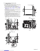
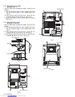
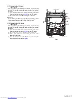
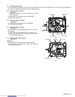
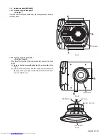
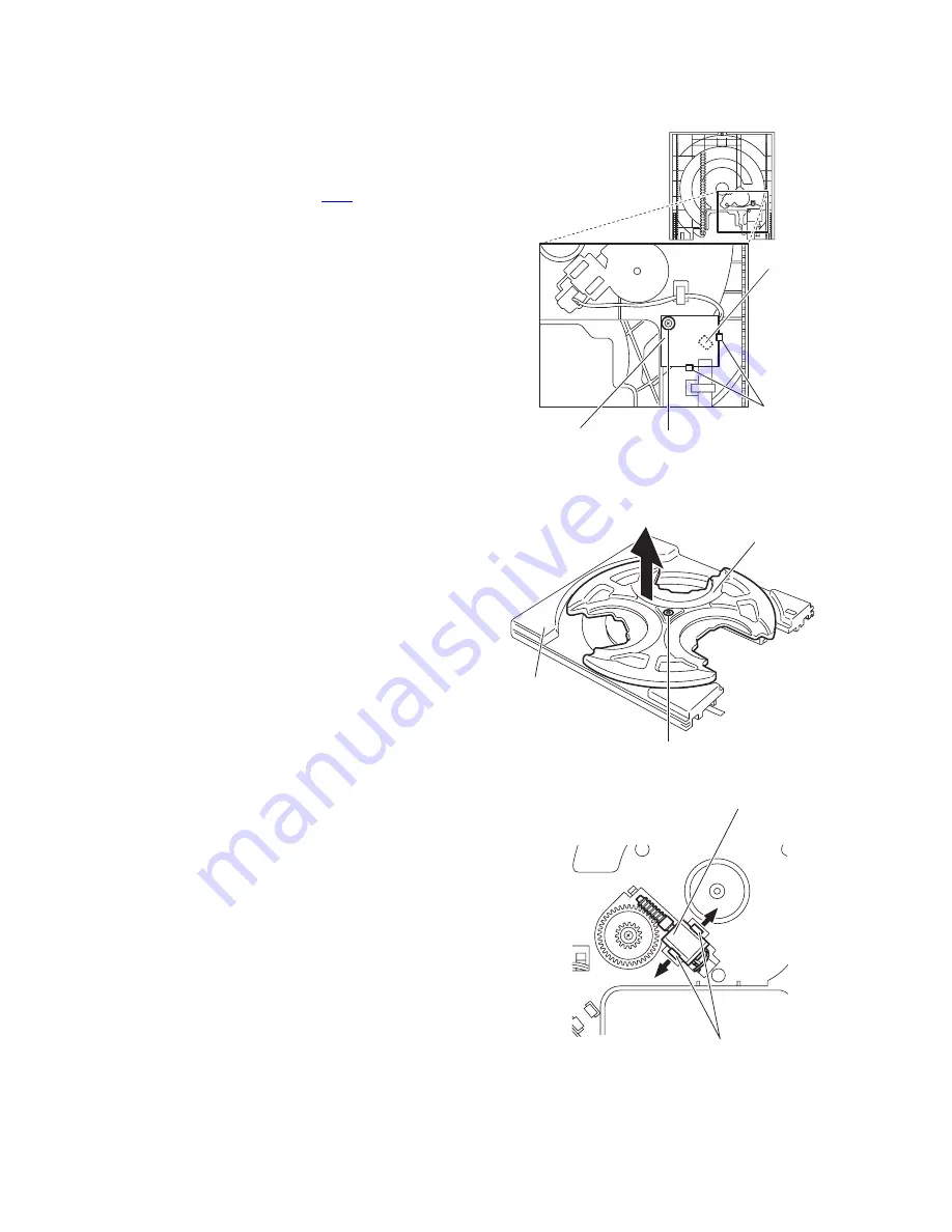
3.2.3 Removing the sensor board
(See Fig.5)
• Prior to performing the following procedures, remove the tray
disc.
(1) Remove the screw
A
attaching the sensor board on the
tray disc.
(2) Remove the sensor board releasing the two tabs
a
.
(3) Disconnect the wire from the connector
CW1
on the sensor
board.
Fig.5
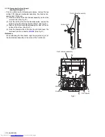
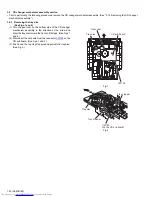
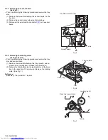
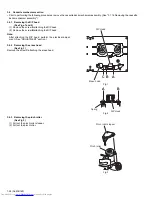
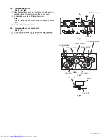
3.2.4 Removing the loading motor
(See Figs.6 and 7)
• Prior to performing the following procedures, remove the tray
disc and sensor board.
(1) Remove the screw
B
attaching the tray roulette and re-
move the tray roulette from the base tray. (See Fig.6.)
(2) Release the tabs
b
attaching the loading motor on the base
tray in the direction of the arrow and remove the loading
motor. (See Fig.7.)
Reference:
Base tray + Tray roulette = Tray disc
Fig.6
Fig.7
CW1
Sensor board
Tray disc (reverse side)
Tab
a
A
Base tray
Tray roulette
B
Loading motor
Tabs
b
Base tray (upper side)
Summary of Contents for CA-MXGB5
Page 45: ... M E M O ...
Page 46: ...2 1 Wiring diagram ...
Page 47: ...2 2 ...
Page 50: ...2 5 Standard schematic diagrams Main section MX GB6 ...
Page 53: ...2 8 safety assurance parts placing those parts make se the specified one ...
Page 54: ...2 9 Main section MX GB5 ...
Page 58: ...2 13 FL Key control section common ...
Page 59: ...2 14 ...
Page 60: ...2 15 CD section common ...
Page 61: ...2 16 ...
Page 62: ...2 17 Printed circuit boards Main board ...
Page 63: ...2 18 Amp board ...
Page 64: ...2 19 Front board ...
Page 65: ...2 20 CD board ...

