(No.MB160)1-33
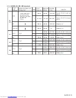
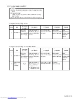
4.1.2 AM (MW), LW, SW1, SW2 adjustment
Circuit
to be
Adjusted
Measuring Instrument &
Arrangement
Step
S.S.G
Frequency
Radio dial
Setting
Adjusting
Point
Adjust for
1
522kHz
522kHz
MW OSC
Adjust for 1.0V±0.1V at the low.
(IR117)
2
1611kHz
MW OSC
AM
(MW)
RF
1
594kHz
594kHz
MW ANT
Maximum out
INTER FREQ
1
455kHz
522kHz
TL2
Maximum out
OSC
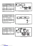
Fig.4
1
146kHz
LW OSC
LW
2
290kHz
RF
1
150kHz
150kHz
LW ANT
OSC
Fig.4
1
2.3MHz
SW1 OSC
SW1
2
7.3MHz
-
RF
1
3.5MHz
3.5MHz
SW1 ANT
OSC
Fig.4
1
9.5MHz
SW2 OSC
SW2
2
26.1MHz
-
RF
1
10MHz
10MHz
SW2 ANT
OSC
Connect AM signal
generator to loop
antenna,VTVM AND
oscilloscope
(Fig.4)
Check for 7.0V±1.0V at the high.
(IR117)
1611kHz
LW OSC
Adjust for 2.0V±0.1V at the low.
Check for 7.0V±1.0V at the high.
Maximum out
Adjust for 1.0V±0.1V at the low.
Check for 8.5V±1.0V at the high.
Maximum out
Adjust for 1.5V±0.1V at the low.
Check for 8.0V±1.0V at the high.
Maximum out
Summary of Contents for CA-MXGB5
Page 45: ... M E M O ...
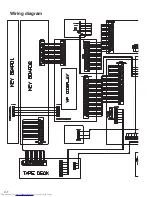
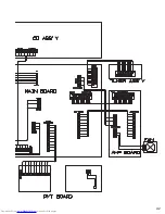
Page 46: ...2 1 Wiring diagram ...
Page 47: ...2 2 ...
Page 50: ...2 5 Standard schematic diagrams Main section MX GB6 ...
Page 53: ...2 8 safety assurance parts placing those parts make se the specified one ...
Page 54: ...2 9 Main section MX GB5 ...
Page 58: ...2 13 FL Key control section common ...
Page 59: ...2 14 ...
Page 60: ...2 15 CD section common ...
Page 61: ...2 16 ...
Page 62: ...2 17 Printed circuit boards Main board ...
Page 63: ...2 18 Amp board ...
Page 64: ...2 19 Front board ...
Page 65: ...2 20 CD board ...

