1-18 (No.MB160)
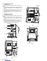
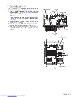
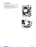
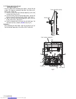
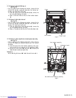
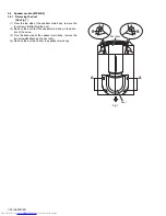
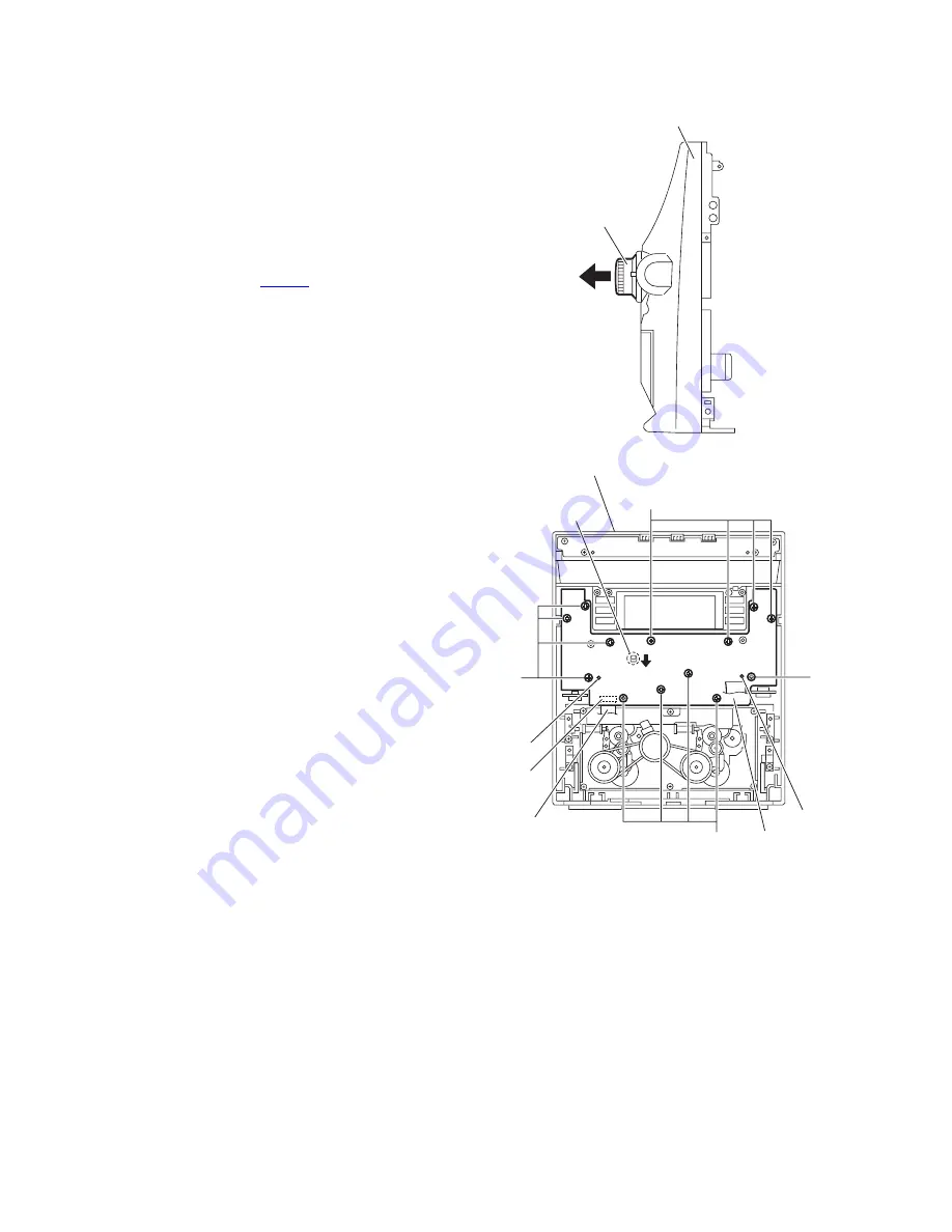
3.1.13 Removing the front board
(See Figs.30 and 31)
• Prior to performing the following procedures, remove the top
cabinet, CD changer mechanism assembly, front cabinet as-
sembly and VFD board.
(1) From the outside of the front cabinet assembly, pull out the
volume knob. (See Fig.30.)
(2) From the inside of the front cabinet assembly, remove the
thirteen screws
Y
attaching the front board. (See Fig.31.)
(3) Take out the front board while releasing the claw
i
in the di-
rection of the arrow. (See Fig.31.)
(4) From the forward side of the front board, disconnect the
card wire from the connector
UCW06
. (See Fig.31.)
Reference:
When attaching the front board, align the projections (
j
,
k
) of
the front cabinet assembly in the holes of the front board.
Fig.30
Fig.31
Volume knob
Front cabinet assembly
k
j
i
Front cabinet assembly
UCW06
Cord wire
Front board
Y
Y
Y
Y
Summary of Contents for CA-MXGB5
Page 45: ... M E M O ...
Page 46: ...2 1 Wiring diagram ...
Page 47: ...2 2 ...
Page 50: ...2 5 Standard schematic diagrams Main section MX GB6 ...
Page 53: ...2 8 safety assurance parts placing those parts make se the specified one ...
Page 54: ...2 9 Main section MX GB5 ...
Page 58: ...2 13 FL Key control section common ...
Page 59: ...2 14 ...
Page 60: ...2 15 CD section common ...
Page 61: ...2 16 ...
Page 62: ...2 17 Printed circuit boards Main board ...
Page 63: ...2 18 Amp board ...
Page 64: ...2 19 Front board ...
Page 65: ...2 20 CD board ...

