– 25 –
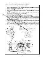
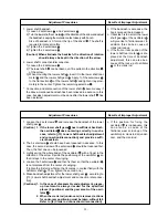
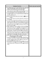
1. Lower shaft backlash
1) Loosen 2 setscrews
and 2 setscrews
.
2) Turn the lower shaft rear metal
in the direction of the arrow and adjust
the backlash, keeping the metal to contact closely with Face A.
Size of backlash is 0.1mm at the tip of the driver
. The shaft is
required to rotate smoothly.
3) Tighten the 2 setscrews
.
4) Tighten the 2 setscrews
.
(Caution) When eliminate the backlash, the direction of rotation
should always be kept in the direction of the arrow.
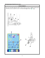
2. Lower shaft connection/disconnection
1) Loosen the 2 setscrews
.
2) The lower shaft
can be taken out if it is pulled in the direction
C
of the arrow.
3) When mounting the lower shaft
, insert it in the lower shaft rear
metal
and the lower shaft gear
. Apply 1 of the setscrews
to the flat section
of the lower shaft
and tighten it approxi-
mately in the center. Tighten the remaining setscrew
.
* Connection and disconnection of the lower shaft
become easy if
the above-mentioned backlash has been relieved in advance. In this
case, backlash adjustment must be done after the lower shaft
has
been installed.
o If the backlash is excessive, the
hook noise will be increased.
o If backlash is too small, the lower
shaft gear
or the oscillator
will give rise to frictional wear. In
addition, this can be a cause of
crank rod lock-up.
o If the front or rear position of the
lower shaft rear metal
is dis-
placed at the time of backlash
adjustment, this can also be a
cause of the lock-up of oscillator
or the crank rod.
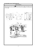
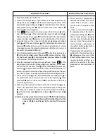
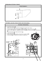
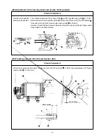
1. Loosen the 2 setscrews
and increase the backlash of the lower
shaft gear
.
(Caution) 1. If the lower shaft gear
has insufficient backlash,
the oscillator
does not swing correctly. In such a
case, refer to [(13) Lower shaft backlash adjustment
and connection/disconnection] and provide a suffi-
cient backlash.
2. The 3 setscrews
should have been loosened in advance. In this
case, the second screw of the setscrews
should be loosened first.
Then, the first one can be loosened.
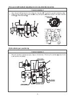
3. Lightly swing the whole body of the oscillator
with a finger in the
direction of the arrow. Decide the positioning of the oscillator
so
that it stays in the center of swinging.
4. Loosen the 3 setscrews
and then fix them so that the oscillator
is not displaced from the center of swinging.
(Tighten the first screw first so that it comes in contact flatly with the
oscillator shaft
. Then, tighten the second one.)
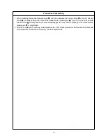
5. Make backlash adjustment for the lower shaft gear
, according to
[(13) Lower shaft backlash adjustment and connection/ disconnec-
tion].
(Cautions) 1. In the case of disassembly and adjustment, grease-
up treatment is always needed for the specified
places (2 positions) and the gear area A of the oscil-
lator
.
2. When the crank rod (under-cam) is removed, actions
for under-cam positioning must be taken, without fail.
Refer to [(6) Crank rod connection/ disconnection].
o If the position for fixing the
oscillator
is inadequate, this
can also be a cause of the
frictional wear or lock-up of the
oscillator pin, crank rod lid, under-
cam, and the crank rod.
Adjustment Procedures
Results of Improper Adjustment
Adjustment Procedures
Results of Improper Adjustment


