background image

– 115 –

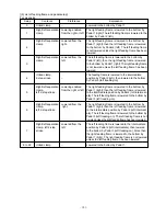
[Sewing Machine Driving Status Diagram of the Port I/O]

[Check Program Status Diagram of the Port I/O]

50ms

120ms

120ms

49: Needle upper position

50: Needle lower position

51: Needle upper dead point position  

52: Needle lower dead point position 

53: Thread trimming signal  

54: During rotation  

55: Sewing machine brake 

102: Sewing machine start

103: Sewing machine stop

 Intermediate presser lowering

20ms

Intermediate presser lifting 

Wiper driving

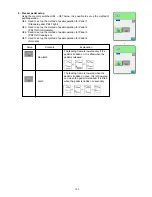
Output check program SW ON 

Intermediate presser check 
program SW 

Start SW ON

Ready SW ON

Reset SW ON 


Presser thread trimming check program SW ON 
Needle thread clamp check program SW ON

XY check program SW ON

57: Setting condition

74: Presser SW input effective 

75: Start SW input effective 

102: Sewing machine start  

103: Sewing machine stop

104: Jump feed start 

106: Total presser lowering 

107: Total presser lifting 

73: Check program state

51: Sewing start wait  

52: XY driving wait  

53: Sewing machine start wait 

54: Sewing machine stop wait  

55: Feeding frame lift/lower wait  

50: Start SW input prohibited 


49: Presser SW input prohibited 

Start SW ON

Start SW ON

Sewing machine check 
program SW ON


Summary of Contents for AMS-221EHL

Page 1: ...40049827 No E374 02 ENGINEER S MANUAL Computer controlled Cycle Machine With Input Function AMS 221E Series ...

Page 2: ...n which are not covered in the Instruction Manual It is advisable to use the Input Instruction Manual relevant Instruction Manual and Parts List together with this Engineer s Manual when carrying out the maintenance of these machines In addition for the motor for the sewing machine with thread trimmer refer to the separate Instruction Manual or This manual gives the Standard Adjustment on the form...

Page 3: ... Adjusting the thread trimmer sensor 34 22 Adjustment of the moving knife and counter knife position 36 23 Floating amount of the thread tension disk 36 24 Second thread tension connection disconnection 38 25 AT unit connection disconnection 40 26 Wiper adjustment 42 27 Backlash adjustment for the X motor 44 28 Backlash adjustment for the Y motor 44 29 Tension adjustment for the X timing belt 46 3...

Page 4: ...p 166 8 Table of exchanging gauge parts according to sewing specifications and needle size used 167 9 Option list 168 1 Method of pedal switch cable set connections 175 10 Maintenance 177 1 Replacing the fuse 177 2 Changing the voltage specification 178 3 Application of grease and Locktight 179 4 Parts to which grease Locktight is applied 180 5 Replenishing the designated places with grease 189 11...

Page 5: ...educed on the X axis Y axis independently when sewing a pattern function 1 to 400 times 0 1 steps Pattern enlargement reduction can be done by increasing decreasing either 22 Enlarging Reducing method stitch length or the number of stitches When the pattern button is selected the function available is only the adjustment of stitch length 23 Sewing speed limitations 200 to 2 700 rpm Scale 100 rpm s...

Page 6: ...2 Configuration 1 Names of main unit Machine head Wiper switch Temporary stop switch Feeding frame Intermediate presser Thread stand Operation panel IP 410 Power switch Control box Foot pedal Air regulator ...

Page 7: ...e performed COMMUNICATION key Changeover of the data input screen and the communication screen can be performed MODE key Changeover of the data input screen and the mode changeover screen which performs various detail settings can be performed Media card slot Close the cover for use Connector for RS 232C communication Variable resistor for color LCD Screen contrast can be adjusted Adjust it as you...

Page 8: ... 4 3 Standard adjustment 1 Adjustment of the throat plate auxiliary cover height Standard Adjustment Within 0 3mm 1 2516 2 3020 0 8 to 1 0mm ...

Page 9: ... of throat plate aux cover and the lower face of lower plate mounting plate under the conditions that the throat plate aux cover is positioned higher than throat plate and its step difference is kept within 0 3mm Since then fix the setscrews 2 pcs and the setscrews 12 pcs o The feed plate is caught by the stepped part of the throat plate and the throat plate auxiliary cover thus causing deformatio...

Page 10: ...ment of the X movement top cover Standard Adjustment Auxiliary cover rail stop plate 2 Adjustment of the feed bar auxiliary cover rail X Standard Adjustment X movement bottom cover asm X movement bottom cover asm ...

Page 11: ...per amount of grease on the sliding parts of the Y guide rail holder o If there is any rattling this can be a cause of noise o If the rattling condition is removed extremely this can be a cause of abrasion developed in the X movement top cover asm Adjustment Procedures Results of Improper Adjustment 1 Loosen 16 setscrews 2 Lightly push the feed bar auxiliary cover rail X in the direction of the ar...

Page 12: ...Refer to 3 5 Removal of the main shaft motor and coupling 4 Loosen 2 setscrews On this occasion be aware that the balancer may rotate due to loosened setscrews 5 Loosen 2 setscrews 6 Loosen 2 setscrews On this occasion completely remove No 1 setscrew of the setscrews from the flat part of the main shaft 7 Loosen 2 setscrews and 2 setscrews 8 Pull out the main shaft in the direction of Arrow C Scre...

Page 13: ...crews and 2 setscrews Make sure that No 1 setscrew touches the flat part of the main shaft 5 Mount the main shaft motor and coupling Refer to 3 5 Removal of main shaft motor and coupling 6 Secure the eccentric cam of the intermediate presser with 2 setscrews Refer to 3 8 Adjustment of intermediate presser cam 7 Press the hand pulley in the direction of Arrow F to engage the hand pulley gear A with...

Page 14: ... 2 For removal of the coupling from the main shaft motor loosen 2 setscrews on the main shaft motor side Caution The screw hole that can be seen first is No 1 setscrew when the main shaft is turned in the forward direction A A A A A For loosening loosen No 2 setscrew first and for tightening tighten No 1 setscrew first No 1 setscrew No 1 setscrew 0 7mm A No 2 setscrew Procedures of disassembling ...

Page 15: ...al direction 2 For connecting the coupling to the main shaft motor 1 Provide a clearance of 0 7 mm between the coupling and main shaft motor 2 Apply No 1 setscrew of the coupling to the flat section of the main shaft motor the main shaft and secure it 3 For engaging the coupling 1 Position the setscrew No 1 setscrew on the main shaft motor side between 2 setscrews on the main shaft side and engage...

Page 16: ...age No 1 setscrews from the flat section of the oscillator shaft 2 Pull out the oscillator shaft in the direction of Arrow A 3 Remove the main shaft according to 3 4 Main shaft connection disconnection and remove the crank rod unit 22 1 to 22 6mm Face B No 2 setscrew No 1 setscrew C A E D Procedures of disassembling No 1 setscrew No 2 set screw ...

Page 17: ...ft Lightly press the oscillator shaft in the direction of arrow C and the thrust collar in the direction of Arrow D and tighten 2 setscrews Make sure that No 1 setscrew touches the flat section of the oscillator shaft 5 Secure the oscillator according to 3 14 Oscillator gear positioning Caution 1 Make sure that no torque is applied by rotating the main shaft 2 When the crank rod unit is connected ...

Page 18: ...wers and the clearance between the needle bar connecting and needle bar lower bushing is 4 6 mm 2 setscrews of the crank balancer becomes horizontal position Axial direction Bring the main shaft eccentric cam into contact with the crank balancer Standard Adjustment 4 6mm B A ...

Page 19: ...re the crank balancer with 2 setscrews under the condi tions that 2 setscrews securing the balancer are horizontally positioned and the balancer is moved in the direction of Arrow B to make it into contact with the main shaft eccentric cam For tightening 2 setscrews tighten them alternately Adjustment Procedures Results of Improper Adjustment o If the mounting angle of the crank balancer is wrong ...

Page 20: ... 16 8 Adjustment of intermediate presser cam 9 Adjustment of intermediate presser bar 13 5mm Standard Adjustment Standard Adjustment Align Align ...

Page 21: ...ew after ensuring that the needle passes through the center of the intermediate pressure Caution Be aware that the tightening pressure of the setscrew should be from 2 16 to 2 75 N m 22 to 28 kgf cm o An excessive thrusting distance of the intermediate presser bar may damage the intermediate presser spring or cause poor presser lifting o Excessive tightening pressure may deform the intermediate pr...

Page 22: ...ely separate from the flat part of the intermediate presser variable shaft 8 After the intermediate presser variable arm and the intermediate presser variable shaft have been pulled out in the direction of the Arrow B loosen the setscrew and pull out the intermediate presser variable shaft from the intermediate presser variable arm At that time both of the setscrews should be separated completely ...

Page 23: ... the intermediate presser lifting shaft in this order and pass this assembly through the frame Mount the E ring on the intermediate presser lifting shaft 7 Pressing the intermediate presser lifting shaft in the direction of the Arrow C press the thrust collar in the direction of the Arrow G and tighten the two setscrews 8 Fix the intermediate presser lifting cam by means of the 2 setscrews so that...

Page 24: ...Standard Adjustment Start the test mode I10 IP 410 When is pressed twice after the completion of origin retrieval there is coincidence between the center of left hole C in the arm and the second screws of the intermediate presser movable arm C C A B D ...

Page 25: ...of the intermediate presser vari able arm is positioned in the center of the arm s left side hole C or below it If the screw seems to have been positioned above the cen ter return to Step 4 and repeat the above mentioned adjustments 7 If the second screw of the intermediate presser variable arm is not positioned in the center or lower loosen the setscrew of the sensor slit and turn this sensor sli...

Page 26: ... 22 12 Intermediate presser drive arm Close contact Intermediate presser bar Approx 3 6mm Standard Adjustment Refer to Instruction Manual 4 7 Intermediate presser height ...

Page 27: ...al 4 After the setscrew has been tightened confirm that there is no backlash in the intermediate presser adjusting arm in the forward and backward directions 5 Finally make adjustments of the intermediate presser stroke Refer to Instruction Manual III MAINTENANCE OF SAWING MA CHINE 1 4 Adjusting the vertical stroke of the intermediate presser o If there is no clearance there will be interference b...

Page 28: ...top position of the lower shaft so that the setscrew settles almost in the center of the flat section of the lower shaft 14 Oscillator gear positioning 1 When the oscillator is lightly swung by a finger in the direction of the arrow the oscillator is fixed in the center position of swinging No 1 screw No 2 screw No 1 screw A Standard Adjustment Standard Adjustment Face A C 0 1mm or less ...

Page 29: ...cillator or the crank rod 1 Loosen the 2 setscrews and increase the backlash of the lower shaft gear Caution 1 If the lower shaft gear has insufficient backlash the oscillator does not swing correctly In such a case refer to 13 Lower shaft backlash adjustment and connection disconnection and provide a suffi cient backlash 2 The 3 setscrews should have been loosened in advance In this case the seco...

Page 30: ...tion pipes and Take them out of the oil tank 4 Loosen 2 setscrews of the clamp in the waste oil pipe and remove the clamp and the setscrew 5 Loosen the setscrew and take out the driver 6 Loosen the setscrew 7 Remove the setscrew and pull out the shuttle race adjust shaft 8 Pull the shuttle in the direction of the arrow C and take it out Standard Adjustment Procedures of disassembling Top surface o...

Page 31: ...uch this can be a cause of frictional wear of the hook race plane or lock up 1 Pass the two lubrication pipes and and the oil drain pipe through the frame and mount the shuttle 2 Hold the lubrication pipes and with the pipe holder and fix them with the setscrews 3 Fix the two lubrication pipes and with the cord clamps and the setscrews At that time make sure not to permit the lubrication pipes and...

Page 32: ... 28 Marker line for DP x 5 Marker line for DP x 17 with needle count higher than 22 Marker line for DP x 17 with needle count lower than 22 17 Adjusting the height of the needle bar Standard Adjustment ...

Page 33: ...ar down to the lowest position loosen the needle bar connection screw and align the upper engraved line on the needle bar with the bottom end of the needle bar lower bushing 2 Change the adjusting position according to needle sizes Caution Be sure that torque is even after adjustment Adjustment Procedures Results of Improper Adjustment ...

Page 34: ... than 22 is used Marker line for DP x 5 needle Marker line for DP x 17 needle with needle count higher than 22 Marker line for DP x 17 needle with needle count lower than 22 DP x 17 needle of which needle count is higher than 22 is used 0mm 0mm Standard Adjustment 0 05 to 0 1mm 7 5mm b A 0 5mm D C ...

Page 35: ...ke an adjustment so that the blade point of the inner hook is aligned with the center of the needle and that the clearance be tween the front end of the driver and the needle is 0 mm be cause the front end of the driver receives the needle to prevent needle bending Then tighten the setscrew securing the driver 6 Make adjustments so that the clearance C in the revolving direction attains 0 3mm to 0...

Page 36: ... to be tightly coupled Pull out the motor shaft in the direction of the arrow straightforward in order not to hurt the bearing At that time the cam may come down Handle it with care not to damage it 20 Thread trimmer and presser origin sensor adjustment At the time of origin retrieval Start Switch ON in the test mode I07 IP 410 the reference holes A and B of the sewing machine frame come in coinci...

Page 37: ...igin sensor adjustment and make sensor adjustments 1 Start the test mode I07 IP 410 2 Tread on the pedal for the retrieval of the thread trimmer and presser bar lifter cam origin 3 Make sure that the standard holes A and B of the thread trimming motor stand are aligned with the standard hole C of the thread trim mer and presser lifter cam using a bar 4 If the standard hole C of the thread trimmer ...

Page 38: ...read trimmer sensor After origin retrieval Start Switch ON in the test mode I07 IP 410 press the key 6 to 8 times until the thread trimmer sensor is turned OFF IP 410 Control panel display changed to B A C Standard Adjustment ...

Page 39: ...rimmer cam Examine the sensor changeover position in the steps 3 and 4 above 6 Repeat the steps 2 to 5 above until the coincidence is secured Caution During adjustments check the clearances A B and C of the sensor slit and the sensor If the clearances seem to be insufficient use the setscrews and to correct the gradient While taking this action continue to work on the steps above Adjustment Proced...

Page 40: ...t end to the tip of the thread cutter lever small is 18 5mm However there shall be a proper clearance toward the moving knife tip during needle thread clamp and feed forward 23 Floating amount of the thread tension disk When the sewing machine power supply is turned off AT solenoid is OFF the gap between AT thread tension disk is 0 6 to 1mm Close contact Standard Adjustment Standard Adjustment 4 m...

Page 41: ...ead tension Confirm that the thread tension disk are closed Caution When the tension releasing pin adjusting collar is rotated the thread section should not be engaged with the incomplete thread section of the thread tension re leasing pin The thrusting distance of the thread ten sion releasing pin should be 4 mm or less from the tension releasing pin adjusting collar If the amount of disc floatin...

Page 42: ...hread tension cap 3 Remove the nut and the tension releasing pin adjusting collar Then take out the thread tension disc pressing plate and three thread tension disc return springs 4 Pull out the second thread tension to remove it Arrow A 5 For reassembly follow the steps of 4 to 1 above Procedures of disassembling A ...

Page 43: ...essing pin If you try to mount the second thread tension forcedly with the pin area left disengaged this may result in breakage in the thread tension pressing pin or malfunction 2 After the completion of mounting make adjustments of 23 Floating amount of the thread tension disk and 47 Adjustment of thread take up spring 1 Stroke adjustments Procedures of assembling ...

Page 44: ...the AT link unit rear Be careful not to drop the washer at that time 3 Lift the AT joint block of the AT unit upward to remove the block from the pin block H type or S type of the AT link unit rear 4 Draw out the AT link unit front from the plane side in the direction of the arrow E and remove it 5 Remove the 2 setscrews and take out the AT solenoid unit 6 For reassembly follow the steps of 5 to 1...

Page 45: ...e AT joint is turned 4 times the feed move amount comes to attain 2mm 3 For the pin block of the AT link unit rear use the pin block for H type and the pin block for S type The wrong pin position may cause AT malfunction resulting in incorrect thread tension 4 After completion of all assembly work make sure that the thrust collar closely contacts with the AT sole noid unit If there is a clearance ...

Page 46: ... plate top surface Height of Intermediate Presser 1mm 10mm 15 to 20 V letter 1 When lowering the intermediate presser at the stop position after thread trimming needle height from the top surface of throat plate is 17 7 mm and pressing wiper link section A adjust the clearance between the center of needle and the inside of V letter of the wiper to 10 mm 2 Press wiper link section A on the way and ...

Page 47: ...longitudinal 10 mm and lateral positions of the wiper Then tighten setscrew o If the clearance between the wiper and needle is too small the wiper comes in contact with the needle due to uneven stop position of the main shaft causing needle breakage o If the clearance between the wiper and needle is excessive the wiper comes in contact with the intermediate presser and the wiper will damage the in...

Page 48: ...Backlash adjustment for the X motor 28 Backlash adjustment for the Y motor Standard Adjustment Standard Adjustment Motor installing base Y drive gear thrust bearing Bed Flat section 40 7 to 40 8mm Flat section ...

Page 49: ...the Y feed stepping motor with the position of the setscrew At that time confirm that the Y drive bevel gear does not move in the axial direction 3 Install the Y feed stepping motor on the bed 4 Press the Y trailing gear in the direction of the arrow to reduce the backlash to zero and tighten 2 setscrews At that time join the flat section of the Y drive shaft with the position of the setscrew o If...

Page 50: ... 46 29 Tension adjustment for the X timing belt 30 Tension adjustment for the Y timing belt Standard Adjustment Standard Adjustment 2mm 9 8N 9 8N 2mm B A B A ...

Page 51: ...nsion is too much this can cause destruction in the Y timing belt o If the tension is too less this can be a cause of feed error Adjustment Procedures Results of Improper Adjustment Adjustment Procedures Results of Improper Adjustment 1 Move the X movement base to left side 2 Move the X movement base forward and backward and let the right side hole of the bed coincide with the position of the adju...

Page 52: ...from the Y drive shaft 32 Phase adjustment for the Y timing belt Standard Adjustment Standard Adjustment 1mm A Flat section Flat section Y timing belt Y LM guide Y drive shaft thrust bearing Y timing belt Y LM guide Flat section B ...

Page 53: ...ghten 2 setscrews At that time 1 of the setscrews should be aligned with the flat section of the Y drive shaft o If there is any rattling this can be a cause of feed error 1 Loosen 4 setscrews 2 Move the X movement base forward and backward two or three times 3 Tighten 4 setscrews When the Y timing belt is adjusted phase adjustments of this Y timing belt should be carried out without fail Caution ...

Page 54: ... 50 33 Adjustment of the X Y mechanism Make adjustments to the dimensions specified below Standard Adjustment 70mm Face A 192mm Butt Face A Butt 70mm 192mm Butt ...

Page 55: ...e X LM guide A to the X movement base and tighten 8 setscrews 2 Adjust the distance to 70mm between the X LM guide A and the X LM guide B and secure parallelism Then tighten 8 setscrews 3 Secure parallelism between the bed processing face A and the X LM guide A Then tighten 8 setscrews Adjustment Procedures Results of Improper Adjustment o If no parallelism is secured this can be a cause of feed e...

Page 56: ...hould be positioned toward the front SM6050660TP The thinner side should be positioned toward the front When the presser foot face plate is moved vertically and then the face plate bearing comes in contact with the spring pin the startup torque slippage torque will be 0 98 to 7 84N 100 to 800g ...

Page 57: ... setscrew is tightened pressure kept applied to the face plate bearing is changed Therefore when the setscrew is tightened examine the amount of the slippage torque 2 The pressure adjusting screw is not attached to the sewing machine Adjustment Procedures Results of Improper Adjustment o If normal pressure is not applied vertical movement of the presser cannot be accomplished normally o If normal ...

Page 58: ...center to center distance is 119 5 0 3mm between the ø5 hole of the presser cylinder and the ø5 hole of the cylinder knuckle Adjust the center to center distance to 111 5 0 3mm between the 2 step stroke fulcrum shaft and the connecting shaft of the intermediate stop cylinder knuckle when the intermediate stop cylinder 2 step stroke cylinder assumes a state of maximum stroke 111 5 0 3 at the maximu...

Page 59: ...etely As a result the material cloth cannot be held tight and displacement of materials can occur 1 Pull the knuckle so that the 2 step stroke cylinder can attain the maximum stroke 2 Loosen the nut and turn the knuckle so that the center to center distance is adjusted to 111 5 0 3mm 3 Fix the nut assuredly o If the center to center distance is insufficient the amount of presser rise cannot attain...

Page 60: ...d tighten the nut Standard adjusting value of the speed controller for the 2 step stroke cylinder 1 Loosen the nut and once turn the knob fully in Direction A Then turn this knob in Direction B by one turn and tighten the nut Standard Adjustment For presser cylinder right For presser cylinder left Type L 2 step presser with 2 step stroke For 2 step stroke cylinder For presser cylinder right For pr...

Page 61: ...ncrease the vertical presser speed turn the knob in Direction B o To decrease the vertical presser speed turn the knob in Direction A o Too much noise is generated when the presser is lowered o The presser does not rise Adjustment Procedures Results of Improper Adjustment ...

Page 62: ... cylinder right can rise at the same time Then tighten the nut 2 At that time confirm that the pressure reducer of for the presser cylinder right has reduced the pressure to 0 10 to 0 17Mpa If the pressure seems to deviate from this range check the torque at the working section of the feed bracket and readjust this deviation Caution For Type S specification for united presser only the pressure red...

Page 63: ...to the standard adjusting values o To reduce the pressure turn the knob in Direction B o To raise the pressure turn the knob in Direction A o The presser cannot be lowered by hand Adjustment Procedures Results of Improper Adjustment ...

Page 64: ... gauge 40 Adjusting the X origin sensor When the feed is in the mechanical origin align the tip of the needle with the lateral position of the engraved dot of the origin A D C Standard Adjustment Standard Adjustment Origin marking for 2516 B Y movement base 174mm 3020 116mm 3020 Origin marking for 3020 ...

Page 65: ...n the 2 setscrews 5 When the engraved marking of the origin is found to be displaced in Direction B from the needle tip loosen the 2 setscrews and adjust the sensor mounting plate in Direction D After adjustments tighten the 2 setscrews Caution After the adjustment make sure that the slit plate does not interfere with the sensor Adjustment Procedures Results of Improper Adjustment Adjustment Proce...

Page 66: ... 41 Adjusting the Y origin sensor When the feed is in the mechanical origin align the tip of the needle with the longitudinal position of the engraved dot of the origin Standard Adjustment A B C D Sensor Y ...

Page 67: ...g of the origin is found to be displaced in Direction A from the needle tip adjust the sensor mounting plate in Direction C Loosen the setscrews and fix the setscrews after adjustments 5 When the engraved marking of the origin is found to be displaced in Direction B from the needle tip adjust the sensor mounting plate in Direction D Loosen the setscrews and fix the setscrews after adjustments Adju...

Page 68: ... bobbin winder amount The position of the bobbin winder lover is based on the standard that it is 14 mm apart from the bobbin winder shaft Try to perform bobbin winding actually and make fine adjustments of the bobbin lever set screw in the directions of the arrows A and B so that the amount of thread winding becomes adequate recommended value 80 to 90 of the bobbin Standard Adjustment Standard Ad...

Page 69: ...the amount of winding 1 If the amount of winding seems to be too much adjust the bobbin winder lever in the direction of the arrow B 2 If the amount of winding seems to be too less adjust the bobbin winder lever in the direction of the arrow A 3 If the winding state of the thread around the bobbin winder seems to be uneven loosen the nut and adjust the height of the thread tension control Example ...

Page 70: ...he direction of the arrow E After the best positioning has been secured fasten the 2 setscrews Caution If Part B B B B B and F F F F F is damaged this is the cause of thread breakage hangnail of thread stain on thread etc Therefore this part should be polished by the use of a buff or the like In particular the rear side should be handled with care 45 Shuttle felt Two pieces of the shuttle felt are...

Page 71: ...the moving knife to fail to hook the needle thread o Too much motion to the left side will cause the moving knife to fail to hook the bobbin thread 1 If the shuttle felt seems to be protruded or it has been replaced with a new one push it in by means of tweezers or the like Caution Do not push it in excessively Align the height and the plane of the shuttle race 2 Confirm that the shuttle packing h...

Page 72: ... A 0 3m m Stroke The movable distance of the needle thread when the needle thread is pulled in the direction A until the thread take up spring stops 12 to 15 mm for S type 12 to 18 mm for H type Tension Adjust the thread take up spring tension in accordance with the thread tension Actually sew a material and adjust the thread take up spring tension to an appropriate value Standard Adjustment Stand...

Page 73: ...of remaining needle thread is shortened causing the needle thread to slip off the needle at the sewing start o If the stroke of the thread take up spring is smaller than the speci fied value Needle thread breakage will oc cur at the time of thread trimming when using a thin thread Caution If the thread take up spring interferes with the L shaped thread guide the thread take up spring may fail to r...

Page 74: ...rew cannot be seen from the open part of the needle thread clamp device try to move the needle thread clamp connector link by hand in the direction of A or B 2 Remove the 4 setscrews of the needle thread clamp base and take out the needle thread clamp device Open part A B Procedures of disassembling ...

Page 75: ...to the most advanced position Confirm that the distance to the needle thread clamp support plate asm and also to the needle is 3 3 to 3 7mm and 1 7 to 2 3mm respectively 5 If the distance seems to be inadequate loosen the four setscrews and move the needle thread clamp device for adjustment 6 After the completion of the above mentioned reassembly make adjustments according to 49 Adjusting the need...

Page 76: ...1 The needle thread clamping position is defined by pressing the key after origin retrieval in the test mode I08 IP 410 This position is defined where it is returned by one step from the most advanced position 2 According to the thread clamp specifications the memory switch U69 may change S Type 0 H Type 1 49 Adjusting the needle thread clamp sensor Standard Adjustment C B A 3 3 to 3 7mm 1 7 to 2 ...

Page 77: ... the above mentioned steps 2 to 4 6 Using 3 to 4 pulses repeat the steps 2 to 5 above until the clear ance A becomes 0 7 Tread on the pedal for needle thread clamp origin retrieval and define the most advanced position by pressing the key once 8 Confirm that the distances between the needle thread clamp support plate complete and the needle are kept at 3 3 to 3 7mm and 1 7 to 2 3mm respectively 9 ...

Page 78: ...hread clamp base becomes 21mm for S Type and 16 5mm for H type Standard Adjustment 2 Needle thread clamp notch F position When the needle thread clamp link complete is pressed in Direction C and Part B of the needle thread clamp support plate complete and the needle thread clamp begins to open the distance between the needle thread clamp and the needle thread clamp base becomes 23mm for S Type and...

Page 79: ...edle thread clamp and the needle thread clamp base the needle thread release timing becomes earlier and this can be a cause of unthreading at the beginning of sewing o If the distance is too short be tween the needle thread clamp and the needle thread clamp base the needle thread release tim ing is delayed and this can be a cause of needle thread end re maining on the rear side of the material o I...

Page 80: ...h data level 2 2 To select the memory switch button to be changed Select the data item D to be changed using the up and down scroll buttons C 3 To change memory switch data level 2 Memory switch data level 2 has 2 types of data items one is where a value is changed and the other is where a pictograph is selected The data items where a value is changed are colored pink and num bered such as and the...

Page 81: ... stitch 200 to 2700rpm 100rpm 2700 In case of with thread clamp 7 Thread tension of 1st stitch 0 to 200 1 200 In case of with thread clamp 8 Thread tension setting at the time 0 to 200 1 0 of thread trimming 9 Thread tension changeover timing 6 to 4 1 4 0 at the time of thread trimming 10 Sewing speed of 1st stitch 200 to 1500rpm 100rpm 200 In case of without thread clamp 11 Sewing speed of 2nd st...

Page 82: ...out buzzer sound 1 Panel operating 2 18 Buzzer sound can be prohibited sound 2 Panel operating sound error 19 Number of stitches of thread clamp 1 to 7 stitches 1 2 release is set 20 Clamping timing of thread clamp can 10 to 0 1 4 be delayed 0 21 Thread clamp control can be 0 Normal prohibited 0 1 Prohibition No Item Setting range Initial value HL HS SL HL HS 2516 2516 2516 2516 3020 FU06 SS 2516 ...

Page 83: ...f sewing can be set 0 1 Wuthout presser up Origin retrieval can be performed 0 Without origin 25 every time after end of sewing retrieval 0 other than cycle sewing 1 With origin retrieval 26 Origin retrieval in cycle sewing can 0 Without origin be set retrieval 1 Every time 1 0 pattern is finished 2 Every time 1 cycle is finished 27 Start of presser when sewing machine stops by temporary stop 0 Pr...

Page 84: ... 32 Motion method of wiper can be selected 1 1 Enabled Unit of sewing shape size change 0 input 33 can be selected 0 Function for IP 410 only 1 Actual size input 34 Thread tension output time when 0 to 20 1sec 1sec 0 needle thread tension setting can 0 No thread be set tension output 35 Bend position of thread clamp is 0 S type 1 S type 0 H type 1 selected 1 H type thin thread 50 to 8 2 H type int...

Page 85: ...eft separate type frame no preference between right and left 2 Right left separate type frame order right left 3 Right left separate 40 Feeding frame control pedal type frame order left right 1 0 5 0 6 open close 4 Integrated type stroke 5 Right left separate type left stroke no preference between right and left 6 Right left separate type left stroke order right left 7 Right left separate type lef...

Page 86: ... type 1 0 5 0 6 midway stop time open close frame stroke 5 Right left separate type left stroke no preference between right and left 6 Right left separate type left stroke order right left 7 Right left separate type left stroke order left right 8 99 Integrated type frame 0 Without 42 Pedal SW 1 with without latch 1 1 With 0 Without 43 Pedal SW 2 with without latch 1 0 1 0 1 With 0 Without 44 Pedal...

Page 87: ...lel move 2 2 Second origin specified later 0 Without motion 48 Retainer compensation motion 0 selection of motion 1 With motion Selection of needle upper dead point 0 Without 49 at the time of origin retrievaly return 0 1 o origin 1 With 0 Automatic thread trimmer 50 Temporary stop thread trimming 1 operation 1 Manual thread trimmer by pressing stop SW again No Item Setting range Initial value HL ...

Page 88: ...tely before sewing 53 Intermediate presser lowering machine head 0 activation 1 Synchronization with last feeding frame 0 Above intermediate presser 54 Intermedia presser wiper sweeping 1 Above intermediate 1 position presser intermediate side sweeping wiper wearing presser lowest position 2 Below intermediate presser 0 without 55 With without air pressure detection 1 1 with No Item Setting range ...

Page 89: ...hout needle cooler control 1 1 With Greas up error Counted by 1 stitch 58 Clearing of number of stitches of Only clear is grease up is performed available 1 Japanese 59 Language selection 2 English 1 1 3 Chinese No Item Setting range Initial value HL HS SL HL HS 2516 2516 2516 2516 3020 FU06 SS 2516 SS 3020 SL 2516 FU06 S m a l l e s t changeable unit ...

Page 90: ... 0 400rpm 5 Thread trimming speed 1 1 800rpm 0 Ineffective 6 Selection of thread trimming jump 1 feed control 1 Effective 7 Needle hole guide diameter at 1 6 to 4 0mm 0 2mm S tyoe 1 6 H type 2 0 controlling thread trimming jump feed 8 Thread trimmer control prohibition 0 Normal operation selection 0 1 Prohibited to use 9 Output time of magnet wiper on 10 to 500ms 10ms 50 Level 2 This model require...

Page 91: ...ection of automatic 0 Ineffective preparation at power on 0 1 Effective 17 Selection of needle bar stop 0 Ineffective holding mode 0 1 Effective 18 Thread tension output while 0 No output with thread wiper output is active trimming tension kept 0 1 Maximum output 19 Selection between motor presser 0 Motor presser and pneumatic presser 1 1 Pneumatic presser 20 Pneumatic presser lowering delayed tim...

Page 92: ...1 Use 0 Standard Origin retrieval under normal 1 Inversion 24 conditions origin reset route 0 1 selection 2 Y axis X axis 3 X axis Y axis 0 Standard 1 Inversion 25 Origin retrieval at mealing 0 1 origin reset route selection 2 Y axis X axis 3 X axis Y axis 26 Thread trimming timing 2 to 2 1 0 27 Constant reading of pattern in 0 Disabled backup Media data enabled 0 1 Enabled No Item Setting range I...

Page 93: ...iate presser rising speed 100 to 3000pps 10pps 3000 0 Without 34 Material end detection control Y N 1 1 With 0 Without 35 Inversion device control Y N 1 1 With 36 Automatic inversion device Y axis 0 to 100 0mm 0 1mm 17 0 37 XY inching control first step time 100 to10000ms 10ms 400 38 XY inching control second step time 100 to 10000ms 10ms 1200 39 XY inching control max speed 100 to 2000pps 10pps 1...

Page 94: ...000 47 XY feed speed retainer compensation 100 to 10000pps 10pps 2000 48 XY feed moving speed at origin retrieval 100 to 10000pps 10pps 2000 49 XY feed moving speed direction dependence 100 to 10000pps 10pps 10000 first region X axis neighborhood 50 XY feed moving speed direction dependence 100 to 10000pps 10pps 10000 second region Y axis neighborhood 51 XY feed moving speed direction dependence 1...

Page 95: ...t 0 to 199 1 0 0 LOW 57 301 Input terminal 1 active 0 1 HIGH 58 302 Input terminal 2 assignment 0 to 199 1 0 0 LOW 59 303 Input terminal 2 active 0 1 HIGH 60 304 Input terminal 3 assignment 0 to 199 1 0 0 LOW 61 305 Input terminal 3 active 0 1 HIGH 62 306 Input terminal 4 assignment 0 to 199 1 0 0 LOW 63 307 Input terminal 4 active 0 1 HIGH No Item Setting range Initial value HL HS SL HL HS 2516 2...

Page 96: ...put terminal 7 active 0 1 HIGH 70 314 Input terminal 8 assignment 0 to 199 1 0 0 LOW 71 315 Input terminal 8 active 0 1 HIGH 72 316 Input terminal 9 assignment 0 to 199 1 0 0 LOW 73 317 Input terminal 9 active 0 1 HIGH 74 318 Input terminal 10 assignment 0 to 199 1 0 0 LOW 75 319 Input terminal 10 active 0 1 HIGH No Item Setting range Initial value HL HS SL HL HS 2516 2516 2516 2516 3020 FU06 SS 2...

Page 97: ...put terminal 13 active 0 1 HIGH 82 326 Input terminal 14 assignment 0 to 199 1 0 0 LOW 83 327 Input terminal 14 active 0 1 HIGH 84 328 Input terminal 15 assignment 0 to 199 1 0 0 LOW 85 329 Input terminal 15 active 0 1 HIGH 86 330 Input terminal 16 assignment 0 to 199 1 0 0 LOW 87 331 Input terminal 16 active 0 1 HIGH No Item Setting range Initial value HL HS SL HL HS 2516 2516 2516 2516 3020 FU06...

Page 98: ...tput terminal 3 active 0 1 HIGH 94 338 Output terminal 4 assignment 0 to 199 1 7 0 LOW 95 339 Output terminal 4 active 0 1 HIGH 96 340 Output terminal 5 assignment 0 to 199 1 9 0 LOW 97 341 Output terminal 5 active 0 1 HIGH 98 342 Output terminal 6 assignment 0 to 199 1 0 0 LOW 99 343 Output terminal 6 active 0 1 HIGH No Item Setting range Initial value HL HS SL HL HS 2516 2516 2516 2516 3020 FU06...

Page 99: ...t terminal 9 active 0 1 HIGH 106 350 Output terminal 10 assignment 0 to 199 1 0 0 LOW 107 351 Output terminal 10 active 0 1 HIGH 108 352 Output terminal 11 assignment 0 to 199 1 0 0 LOW 109 353 Output terminal 11 active 0 1 HIGH 110 354 Output terminal 12 assignment 0 to 199 1 0 0 LOW 111 355 Output terminal 12 active 0 1 HIGH No Item Setting range Initial value HL HS SL HL HS 2516 2516 2516 2516 ...

Page 100: ...ive 0 1 HIGH 118 362 Output terminal 16 assignment 0 to 199 1 0 0 LOW 119 363 Output terminal 16 active 0 1 HIGH 120 364 Virtual I O terminal 1 assignment 0 to 199 1 0 0 Input 121 365 Virtual I O terminal 1 I O selection 0 1 Output 122 366 Virtual I O terminal 2 assignment 0 to 199 1 0 0 Input 123 367 Virtual I O terminal 2 I O selection 0 1 Output No Item Setting range Initial value HL HS SL HL H...

Page 101: ...nal 5 I O selection 0 1 Output 130 374 Virtual I O terminal 6 assignment 0 to 199 1 0 0 Input 131 375 Virtual I O terminal 6 I O selection 0 1 Output 132 376 Virtual I O terminal 7 assignment 0 to 199 1 0 0 Input 133 377 Virtual I O terminal 7 I O selection 0 1 Output 134 378 Virtual I O terminal 8 assignment 0 to 199 1 0 0 Input 135 379 âºVirtual I O terminal 8 I O selection 0 1 Output No Item Se...

Page 102: ...al 11 I O selection 0 1 Output 142 386 Virtual I O terminal 12 assignment 0 to 199 1 0 0 Input 143 387 Virtual I O terminal 12 I O selection 0 1 Output 144 388 Virtual I O terminal 13 assignment 0 to 199 1 0 0 Input 145 389 Virtual I O terminal 13 I O selection 0 1 Output 146 390 Virtual I O terminal 14 assignment 0 to 199 1 0 0 Input 147 391 Virtual I O terminal 14 I O selection 0 1 Output No Ite...

Page 103: ...l 16 I O selection 0 1 Output 0 LOW 152 396 Pedal SW1 active 0 1 HIGH 0 LOW 153 397 Pedal SW2 active 0 1 HIGH 0 LOW 154 398 Pedal SW3 active 0 1 HIGH 0 LOW 155 399 Pedal SW4 active 0 1 HIGH 0 LOW 156 400 Start SW active 0 1 HIGH 0 LOW 157 401 Temporary stop SW active 1 1 HIGH No Item Setting range Initial value HL HS SL HL HS 2516 2516 2516 2516 3020 FU06 SS 2516 SS 3020 SL 2516 FU06 S m a l l e s...

Page 104: ...rame ON OFF operational sequence by ordinary pedal operation Using the memory switch U81 it is possible to set up the operational sequence of the feeding frame by ordinary pedal operation In regard to the setup items refer to the 5 List of feeding frame and pedal setup 3 Feeding frame ON OFF operational sequence by a temporary stop command Using the memory switch U82 it is possible to set up the o...

Page 105: ...red to the bottom by Pedal 3 left treading on Right left separation Lowering enabled The right feeding frame is lowered to the bottom by clamp from the right or left Pedal 1 right then the left feeding frame is lowered 5 left 2 step stroke to the intermediate position by Pedal 2 left intermedi ate The left feeding frame is lowered to the bottom by Pedal 3 left treading on Right left separation Low...

Page 106: ...the time of temporary stop Using the memory switch U41 it is possible to set up the timing for feeding frame lifting when it has been set up with a temporary stop command in the pattern data Setup Contents Explanation Lifting The feeding frame is lifted immediately with the temporary stop command Lifted by pedal operation with the temporary Pedal operation stop command Sewing is started by the sta...

Page 107: ...eft intermediate U86 Used to set up the method of pedal operation for Pedal 3 PK47 left treading on U87 Used to set up the method of pedal operation for Pedal 4 Not used Setup Contents Explanation The feeding frame is lowered only if the pedal is trodden on It is lifted when the Non latch pedal is released The feeding frame is lowered when the pedal is trodden on once It is left lowered ven when t...

Page 108: ...he fixed refuge position is not used disabled Fixed refuge position The fixed refuge position is used enabled 2 Fixed refuge position coordinates setup Using the memory switch K117 it is possible to set up the fixed refuge position Coordi nate X Setup Contents Explanation Coordinate X Coordinate X of the Coordinate X of the fixed refuge position is fixed refuge position set up within the feeding f...

Page 109: ... the feeding frame 1 It is not always necessary to set up the memory switch K90 because the fixed refuge position mode is automati cally secured for the bank function 2 The fixed refuge position defined by the fixed refuge position Coordinate X of Memory Switch K117 and the fixed refuge position Coordinate Y of Memory Switch K118 is regarded as the standby position of the feeding frame for the ban...

Page 110: ...played 2 Registration of the direct pattern number When the direct pattern number registration button C is pressed for a setting input terminal num ber B the direct pattern number selection screen is displayed However the selectable direct pattern num bers are limited only for the individual sewing The direct pattern number to be registered for the input terminal is selected as indicated by D 3 Ba...

Page 111: ...rned ON When the key is pressed the bank mode screen is displayed When the presser is lowered the direct pattern sew ing screen is displayed and sewing can be carried out For the direct patterns to be displayed on the sew ing screen the pattern numbers are automatically changed over if there is coincidence of an input with the relevant input terminal F F AMS 221E AMS 221E ...

Page 112: ... H L Bank No 14 H H L H Bank No 3 H L L H Bank No 7 L H L H Bank No 11 L L L H Bank No 15 H H L L Bank No 4 H L L L Bank No 8 L H L L Bank No 12 L L L L Bank No 16 Bank number Bank number Bank number Bank number Relationship between bank input terminals and bank numbers Input terminal Input terminal Input terminal Input terminal H High L Low when bank input active Low ...

Page 113: ...tive with the External Input 8 com mand of the pattern data 42 External input 9 Sewing is suspended until the input terminal becomes active with the External Input 9 com mand of the pattern data 43 External input 10 Sewing is suspended until the input terminal becomes active with the External Input 10 com mand of the pattern data 44 External input 11 Sewing is suspended until the input terminal be...

Page 114: ...pattern data 48 External output 15 Reverse signal output with the External Output 15 command of the pattern data Status of sewing machine head 49 Needle upper position Upper stop position 40 to 62 Always ON shortly after Power ON 50 Needle lower position Internal signal 80 to 123 Always OFF shortly after Power ON 51 Needle upper dead point position Reverse rotation needle lifting position 5 to 30 ...

Page 115: ...Sheet counter carryover being displayed OFF by counter reset For the trigger 97 READY operation start When the READY key is accepted ON for 100ms 98 READY operation end After moving to READY key sewing start point ON for 100ms 99 Sewing start When the Start switch is accepted Normal Midway stop Temporary stop ON for 100ms 100 Before sewing start point reset Before sewing start point reset after pa...

Page 116: ...t reset 102 Sewing machine start 103 Sewing machine stop 104 XY feed start 106 Total presser lowering 107 Total presser lifting 64 Midway stop C 66 Sewing temporary stop 65 Sewing error display stop 105 Origin reset start 68 Origin reset 69 Presser lowering state 70 Bobbin state 71 Main unit input state 72 Shape check state 73 Check program state 76 Temporary stop SW stopped 78 Air pressure loweri...

Page 117: ... sewing start point reset 102 Sewing machine start 103 Sewing machine stop 104 XY feed start 106 Total presser lowering 107 Total presser lifting 64 Midway stop 66 Sewing temporary stop 65 Sewing error display stop 68 Origin reset 105 Origin reset start 76 Temporary stop SW stopped 78 Air pressure lowering stop 79 Stop on account of another error 77 Thread breakage error stop 59 Ready state 80 Sew...

Page 118: ... 100 Before sewing start point reset 101 After sewing start point reset 102 Sewing machine start 103 Sewing machine stop 104 XY feed start 106 Total presser lowering 107 Total presser lifting 72 Shape check state 73 Check program state 105 Origin reset start 67 Jump feed 68 Origin reset 76 Temporary stop SW stopped 78 Air pressure lowering stop 79 Stop on account of another error 77 Thread breakag...

Page 119: ... SW ON Intermediate presser check program SW Start SW ON Ready SW ON Reset SW ON Presser thread trimming check program SW ON Needle thread clamp check program SW ON XY check program SW ON 57 Setting condition 74 Presser SW input effective 75 Start SW input effective 102 Sewing machine start 103 Sewing machine stop 104 Jump feed start 106 Total presser lowering 107 Total presser lifting 73 Check pr...

Page 120: ...he port I O setup screen is displayed 2 Selection of the port I O screen For port I O setup four I O setup screens are avail able A required function number can be set on a relevant screen B Output number setting C Input number setting D Virtual I O number setting E Switch operation prohibition setting Setup screen changeover is possible with the right and left scroll buttons F located on the top ...

Page 121: ... input of the setting function number H in the selected terminal through the ten key I The signal type is selected from High J and Low K In the case of virtual I O number setting it is selected from output and input To make switch operation setting the setup button L is pressed to select the signal type from High M and Low N E L J K H I N M B G F ...

Page 122: ...01651008B ELCO 60 8263 3088 15 002 9P housing HK01651009B ELCO 60 8263 3098 15 002 12P housing HK01651012B ELCO 60 8263 3128 15 002 Use CN79 and CN81 for switch input Use CN80 and CN82 for sensor or switch input CN79 5V 1 2 3 4 5 6 7 8 9 10 3 3K 5V 3 3K 01 GND 02 GND 03 GND 04 GND 05 GND 1 2 3 4 5 6 7 8 09 GND 10 GND 11 GND 12 GND CN82 5V 3 2 1 4 5 6 7 8 9 10 11 12 3 3K 5V 13 GND 5V 14 GND 5V 15 G...

Page 123: ...118 15 001 12P housing HK01651012A ELCO 60 8263 3128 15 001 It is recommended to use the drive transistor with 0 5 A or less even though the rated current is 0 8 A Make sure that the total current is equal or less than 1 A CN84 24V 24V 01 24V 06 24V 11 24V 12 24V 13 24V 14 24V 15 24V 16 24V 07 24V 08 24V 09 24V 10 24V Ic 0 8A 24V Ic 0 8A 24V Ic 0 8A 02 24V 03 24V 04 24V 05 CN83 CN78 1 2 3 4 5 6 1 ...

Page 124: ... from the sewing machine control side Caution The virtual I O port is an internal signal of the sewing machine It cannot be brought out directly to the outside 3 Control operation At the start of simplified program execution operation is sequentially carried out starting from Step No 1 at the intervals of 1ms for each step At the beginning of step execution the con tents of output information setu...

Page 125: ...e simplified program comes in five patterns In the initial state all the patterns are set at OFF When the simplified program setup button B is used each program can be made effective or ineffective Simplified program ineffective Simplified program effective 3 Simplified program editing Simplified program No and the registered num ber of steps are displayed on the program editing button C When this...

Page 126: ...ion screen is displayed The command that is being selected is displayed on the button On the command selection screen the command button G is displayed Press the selecting command button and then press the Enter button H In regard to command descriptions refer to 4 list of simplified program commands 2 Port I O information setup The port status can be set up for the four items as specified below I...

Page 127: ...n be changed The port comes in the four types as specified below Output port No Input port No Virtual I O port No etc Presser SW 1 to 4 Start SW Temporary stop SW The port No button is displayed on the screen Press the button that corresponds to current setting The selection status button is displayed in gray After selection press the Enter button O M L O For output setting press the output button...

Page 128: ...key R and press the Enter button S In regard to the parameters that correspond to the commands refer to 4 list of simplified program com mands Q R S T U 4 Step insertion It is possible to insert a step before the displayed step When the step insertion button T is pressed the command selection screen is displayed Select the command that is required to be inserted and press the Enter button U Then t...

Page 129: ... the sewing screen The simplified program button A is displayed in the sewing screen if this simplified program is avail able The simplified program select screen is pre sented and the effective simplified program button B is displayed Select the simplified program number the status of which is being checked and press the ENTER but ton C The simplified program confirmation screen is pre sented and...

Page 130: ...nation 1 to 99 steps Number of 0 to 9999 stitches Moving to the next step after the lapse of the preset for No of stitches No stitches number of stitches Jumping to the step specified by the skip destination No within the range of the preset number of stitches when either condition specified by input setting is satisfactory OR input 7 JUMP Jump repetition counter Effective Ineffective Skip destina...

Page 131: ...als directly generate outputs with the aid of the simplified program Port I O setting is disabled Simplified Program Setup End DELy o01H to o16H o01L to o16L Delay time Unit of 1ms And or o01H to o16H o01L to o16L i01H to i16H i01L to i16L Pn Program No Number of stitches Unit of 1 stitch STiA Stio v01H to v16H v01L to v16L v01H to v16H v01L to v16L Sn Step No JUMP Rest p1H to p4H sH eH p1L to p4L...

Page 132: ...ified program input i07 Stacker material clamp sensor Simplified program input i08 Virtual I O I O Contents Remarks v01 Output 61 Sewing forwarded v02 Output 102 Sewing machine started v03 Output 100 Before sewing start point reset v04 Output 101 After sewing start point reset v05 Output 105 Before origin reset v06 Input 55 Feeding frame lift lower wait v07 v08 Caution For the descriptions in the ...

Page 133: ...ng till sewing machine start 2 or o06L v03L v05L d 0 Stacker movement ON Waiting till sewing start point reset or origin reset 3 And v03L Sn 11 d 1 To Step 11 if there is no sewing start point reset 4 And v06L v04L d 0 Feeding frame lifting wait ON Waiting till sewing start point reset 5 And i06 d 0 Waiting till stacker movement sensor ON 6 And o07L i07 d 0 Stacker material clamp ON Waiting till s...

Page 134: ...o06 o07 o08 o09 o10 o11 o12 o13 o14 o15 o16 6 Port I O setup sheet Terminal Contents Remarks input i01 i02 i03 i04 i05 i06 i07 i08 i09 i10 i11 i12 i13 i14 i15 i16 Virtual I O I O Contents Remarks v01 v02 v03 v04 v05 v06 v07 v08 v09 v10 v11 v12 v13 v14 v15 v16 ...

Page 135: ...tio v01H to v16H v01L to v16L v01H to v16H v01L to v16L Sn Step No JUMP Rest p1H to p4H sH eH p1L to p4L sL eL d Delay time c Numberofstitches r Repetition counter Step No Co Command Output information High Output information Low Input information High Input information Low Parameter 1 Parameter 2 Remarks 1 2 3 4 5 6 7 8 9 0 1 2 3 4 5 6 7 8 9 0 7 Simplified program setup sheet ...

Page 136: ...gram version C Main program version D Main shaft program version Pressing the cancel button E closes the ver sion information screen and calls up the mode screen 2 To display the detail screen Press the detail screen button F to call up the panel program detail screen G Module H RVL I Checksum Pressing the cancel button J closes the detail screen and calls up the version information screen Pressin...

Page 137: ...ated 2 To select keylock and activate it Select the keylock activation button B on the keylock setting screen and press Then the keylock setting screen closes and keylock becomes activated 3 After closing the mode screen and calling up the data input screen After closing the mode screen and calling up the data input screen PICT C indicating that keylock is acti vated appears on the right of the pa...

Page 138: ... be used for the maintenance personnel level Each data type is as specified below Data name Pict Extension Contents of data Adjustment data Model name 00XXX MSW Data of the memory switches 1 and 2 Example AMS00001 MSW All sewing machine data Model name 00XXX MSP All data maintained by the sewing machine Example AMS00001 MSP Panel program data AP RVL 6 digits HED Program data and display data of th...

Page 139: ...l the data selection screen is displayed In this state it becomes possible to select the ad justing data and all sewing machine data 3 Program rewriting For the IP 410 1 Selection of the data type When the data classification button C is pressed in a communication screen of the mainte nance personnel level the data selection screen is displayed In this state select the panel program data D 2 Selec...

Page 140: ...s been completed If any data writing error screen should be displayed im mediately turn off the power supply and check the check ing items specified below Then take the setup actions again Checking items 1 Did you open the media cover in the middle of data communication from the media card 2 Data of the media card are incorrect or there is no data file 3 The contact point of the media card is cont...

Page 141: ...ation should be established with a personal computer Information about the method of media card formatting is obtainable from the Instruction Manual 2 25 How to Use the Communication Functions Route directory PROG AMS221E MTxxxxxx prg Servo program MAxxxxxx prg Main program AMS210E APxxxxxx IP 410 program APxxxxxx hed APxxxxxx p01 AMxxxxxx i01 AMxxxxxx i10 AMxxxxxx i11 AMxxxxxx i12 AMxxxxxx i13 AM...

Page 142: ... buttons 2 To call up the error history screen Press the error history button B on the infor mation screen to call up the error history screen The error history screen shows the error history of your sewing machine C Chronological recording number D Error code E Cumulative energizing time during error hour Pressing the cancel button G closes the error history screen and calls up the information sc...

Page 143: ...hanges from blue to or ange and there are 5 buttons 2 To display cumulative operating information Press the cumulative operating information button A on the information screen to call up the cu mulative operating information screen The following 4 items are indicated on the cumula tive operating information screen B Cumulative operating time hour C Cumulative thread trimming count D Cumulative ene...

Page 144: ...st sewing from PM 1 When data vector type for test sewing is transmit ted from PM 1 the screen shown at right appears and a needle positioning drawing of transmitted data appears in the center of the screen The color of the needle positioning drawing changes depending on thread tension If the stitch count of transmitted data is too large a needle positioning drawing does not appear 2 Edit of vecto...

Page 145: ...to call up the registration screen Enter the user pattern number to which the test sew ing data is registered with the numeric keypad G 3 Modification to data Press the button A B or C to be changed to call up the numeric keypad Enter a new value and press the enter button D E F D H G 4 Test sewing Press the ready to go switch E to call up the test sewing screen Test sewing is ready 7 data entry s...

Page 146: ...hread tensions adjusted for needle entry positions The follow ing chart shows the colors of lines for thread tensions Thread tension Color 0 to 20 Gray 21 to 40 Purple 41 to 60 Blue 61 to 80 Light blue 81 to 100 Green 101 to 120 Yellow green 121 to 140 Orange 141 to 160 Red 161 to 180 Pink 181 to 200 Black ...

Page 147: ...ton display positions are corrected LCD check Presence of any dot missing is checked for the liq uid crystal display Input signal check The status of switches and sensor inputs is dis played Main motor rpm check When the sewing machine is started at the preset rpm level the measured rpm value is displayed Output check Wiper and air output check is carried out XY motor origin sensor check The statu...

Page 148: ...us of inching operation of the needle thread clamp motor operation of origin retrieval and the needle thread clamp origin and needle thread clamp sensor is displayed Continuous operation When the conditions of continuous operation have been set up the continuous operation mode is as sumed Intermediate presser adjustment The status of inching operation of the intermediate presser motor operation of...

Page 149: ... the touch panel correction screen is displayed 2 Pressing the bottom left position Press the red circle C located at the bottom left of the screen To complete correction press the can cel button B 3 Pressing the bottom right position Press the red circle D located at the bottom right of the screen To complete correction press the cancel button B B D B A C ...

Page 150: ...reen To complete correction press the cancel button B 6 Data saving When all the four points have been pressed the cor rection data are saved At that time the Power OFF Prohibition screen is displayed The power supply must not be turned off while the above mentioned screen is displayed If the power supply is carelessly turned off no cor rection data are saved After data saving the check program sc...

Page 151: ...e LCD check screen is displayed 2 Confirmation of LCD dot missing The LCD check screen is displayed only in one color In this state the LCD should be checked to freedom from dot missing After this confirmation press a proper position on the screen The LCD check screen is closed and the check program screen is displayed A ...

Page 152: ...ensor check screen is displayed 2 Input signal check In the input signal check screen the input condi tions of various sensors can be confirmed For each sensor the input status is displayed as indicated by B The ON OFF conditions are displayed as shown below ON condition OFF condition Using the UP DOWN buttons C display the sensor that has been confirmed A B C ...

Page 153: ...1 SW Pedal Y motor origin sensor Presser 2 SW Pedal Presser motor origin sensor Presser 3 SW Pedal Needle thread clamp motor origin sensor Presser 4 SW Pedal Intermediate presser motor origin sensor Temporary stop SW Presser motor sensor AUDET sensor Needle thread clamp motor sensor ADDET sensor External input 1 DDET sensor External input 2 UDET sensor External input 3 TG sensor External input 4 P...

Page 154: ...sensor No Pictograph Contents of sensor External input 6 External input 12 External input 7 External input 13 External input 8 External input 14 External input 9 External input 15 External input 10 External input 16 External input 11 ...

Page 155: ...e main motor rpm check screen is displayed 2 Main motor operation and measured rpm value check Using the buttons B C the rpm number can be set up When the button D is pressed the sewing machine is operated at the pre set speed At that time the measured rpm value is displayed at E When the SET button F is pressed the sewing machine is stopped A B C E F D ...

Page 156: ...ck button A is pressed on the check program screen the output check screen is displayed 2 Output check The output check screen can be used for the output check of each position Try to press the output check button B While this button is pressed the ON sta tus output is kept generated A B ...

Page 157: ...Air output 1 Air output 10 Air output 2 Air output 11 Air output 3 Air output 12 Air output 4 Air output 13 Air output 5 Air output 14 Air output 6 Air output 15 Air output 7 Air output 16 Air output 8 The output check display provides the following 17 types of positions ...

Page 158: ...XY motor origin sensor check screen is dis played 2 XY motor origin sensor check According to the status of the X Y origin sensor the ON OFF condition of the sensor is displayed in the position of B When the Arrow Mark button C is pressed the X Y motor can be driven by 0 05mm in the direction Caution 1 Using the Start SW origin retrieval of the X Y motors is effected for both shafts A B C ...

Page 159: ...n sensor is displayed in the position of C Using the and keys D E the presser thread trimmer motor can be driven by one pulse When the fixed position moving button F is pressed the presser thread trimmer motor is driven to any of the following fixed positions A pictograph indicating this position is displayed in gray G Presser lifting position H Presser lowering position lowering position during p...

Page 160: ...f the needle thread clamp origin sensor the ON OFF condition of the needle thread clamp sensor is displayed in the position of B Using the and buttons D E the needle thread clamp motor can be driven by one pulse When the fixed position moving button F is pressed the needle thread clamp motor is driven to any of the following fixed positions A pictograph in dicating this position is reversed and di...

Page 161: ...inuous operation In the continuous operation screen the continuous operation mode is set up B Intervals of operation rest time C Origin retrieval at the end of sewing 0 No 1 Every 100 runs 2 Every time D Presser lifting lowering frequency When the READY key is turned ON continuous operation is started If the READY key is turned ON again in the middle of continuous operation continuous operation is...

Page 162: ...on of the interme diate presser origin sensor is displayed in the posi tion of B Using the and buttons C D the intermediate presser motor can be driven by one pulse When the fixed position moving button E is pressed the intermediate presser motor is driven to any of the following fixed positions A pictograph in dicating this position is reversed and displayed F Lower position at the height of 7mm ...

Page 163: ...240V In the signal phase mode the power supply is connected to Pins 4 5 In the 3 phase mode the power supply is connected to Pins 4 5 6 7 Printed wiring board and dip switch 1 Various printed wiring boards 1 FLT T board Single phase 100V 120V 3 phase 200V 240V Pulse generation is carried out for the purposes of power supply rectification noise reduction and the detection of a momentary interruptio...

Page 164: ...wer supply rectification noise reduction and the detection of a momentary interruption C 10 C 9 4 CN1 Power input Power switch CN3 Momentary interruption detection signal MAIN board CN2 Power output MAIN board Since single phase specifications are adopted the power supply is connected to Pins 4 5 ...

Page 165: ...4 4A Fuse fixed to the board For 85V source primary F5 4A Fuse fixed to the board For 33V source primary CN11 Power connector MAIN board 5V 12V 24V 33V 48V DIPSW 2 1 For writing off 2 2 For mode setting off 2 3 For mode setting off 2 4 For mode setting off DIPSW 1 1 For testing off 1 2 For testing off 1 3 For testing off 1 4 Penetration force off CN17 For power supply FLT board CN16 For Main shaft...

Page 166: ... error E731 Logical error in U V W 5 IPM error E901 Error output generation from IPM 6 Undervoltage E813 Source voltage 20 or more 7 Motor reverse rotation E733 Irregular motor revolutions 8 Overvoltage E811 Source voltage 20 or more 9 Power interruption Display disabled Power interruption of 40ms or more 10 Not used 11 85V power system error E903 SDC board fuse F1 blow off 12 33V power system err...

Page 167: ...er pulse motor White CN32 For the SDC circuit board CN79 Optional switch input Red CN73 Y axis pulse motor White CN72 Intermediate presser pulse motor Blue CN84 Pneumatic output Black CN52 For pneumatic switch White CN51 Foot switch White CN47 Wiper White CN75 Thread clamp pulse motor White CN40 For analog pedal not integrated CN71 X feed pulse motor Red CN39 Active tension Yellow CN31 Power SDC c...

Page 168: ...White CN72 Y motor cooling fan White CN71 X motor cooling fan White CN70 Intermediate presser origin white CN69 Temporary stop Black CN64 Presser lifter origin sensor Black CN68 Thread trimming detection Yellow CN67 Safety switch Red CN63 Y feed origin sensor Yellow CN66 Thread trimmer position sensor Red CN62 X feed origin sensor Red CN65 Thresad clamp origin sensor Yellow Thrad clamp position se...

Page 169: ...onnector for production control CN100 Connector for main unit connection LD1 Status display LED Kept blinking during CPU operation CN102 Connector for personal computer connection The D sub 9P cross cable is use CN108 Connector for backlight connection Backlight power supply Inverter Buzzer CN109 Connector for tuch panel connection Backup batteries DIPSW 1 1 For program weiting off 1 2 For program...

Page 170: ...ON on the SDC board 2 If the penetration force is insufficient for thick materi als this switch should be turned ON 3 All other dipswitches should be turned OFF Caution Dipswitch changeover should be done af ter the power supply has been turned off 4 All dipswitches on the MAIN board are turned OFF SDC board MAIN board SW1 SW1 ...

Page 171: ...Needle hole guide B242621000A B242621000C B242621000B B242621000D B242621000G ø1 6 ø1 6 ø2 0 ø2 4 ø3 0 For knit B242621000F With counter bore ø3 0 Shuttle race ring 14103352 14103659 B1817210DAD Needle guard 1 3 mm Needle guard Needle guard 1 7 mm 1 9 mm Shuttle 40014964 40014965 Intermediate presser 40023632 B1601210D0BA B1601210D0CA ø2 2 ø2 7 ø3 5 Tension controller No 2 asm 40010508 40029411 Th...

Page 172: ... work clamp B2591220000 A x B x t preventing slipping 250 x 200 x1 5 Sponge sheet for work clamp B2564223C00 A x B x t 450 x 300 x 1 5 Work clamp material A B2587220000 A x B x t 380 x 240 x 1 Work clamp material B B2588220000 A x B x t 380 x 240 x 1 5 3 Feed plate blank for Feed plate blank with knurl 40052341 A x B x t processing AMS 221E 2516 239 x 353 x 1 2 Feed plate blank without knurl 40052...

Page 173: ...B x t 140 8 x 72 5 x1 Aluminum feed plate inner plate GMU12037000 A x B x t 140 6 x 72 5 x 1 6 Cassette holder Cassette holder fixing plate asm 40052328 AMS 221E 2516 Cassette holder fixing plate asm 40053782 AMS 221E 3020 Cassette holder assy B25822210A0 AMS 221E 2516 Cassette holder assy 40053777 AMS 221E 3020 7 Feeding frame blank Plastic blank AMS 221E 2516 For united presser 40035093 AMS 221E...

Page 174: ... 1 3 C 14103659 A 1 7 D B1817210DAD A 1 9 B A t B A t B A t A No Part No Part name Q ty 1 40032837 Presser foot asm left 1 2 40032835 Presser foot asm right 1 3 SM6061200SP Presser foot setscrew 4 4 WP0651056SD Presser foot washer 4 5 SS7150910TP Outer frame setscrew 4 6 WP0651056SD Outer frame washer 4 7 SM8060812TP Outer frame height adjusting screw 2 8 NM6060003SC Outer frame height adjusting n...

Page 175: ...diate presser relay Specific presser foot left asm B26302150A0 A x B x t metal fittings Relay metal fittings used to install 66 x 58 x 4 the presser of the ASM 206 and 210 Specific presser foot right asm B2630215AA0 A x B x t 66 x 58 x 4 13 Inverting clamp unit FU 06 40048659 14 Inverting intermediate presser Reversal intermediate presser blank B4317220000 A x B x t blank large with knurl 206 x 12...

Page 176: ... installing base B 8 x 24 x 15 This item is required when the reversal intermediate presser blank small B4319220000 is used Reversal intermediate presser small SS1090750SP setscrew 16 Reversal crank shaft Reversal crank shaft B B4326220000 A x B x ø C 26 x 71 x 7 17 Wiper Side sweeping wiper assy 40035867 Side sweeping wiper repeater cable 40036668 assy ...

Page 177: ... 173 Name of parts Type Part No Remarks 18 Pedal switch 3 step pedal PK47 GPK470010AB Relay cable for 3 step pedal 40033875 2 step pedal PK78 40033831 19 Needle cooler 40035692 ...

Page 178: ...is is a kit intended to change 40040138 Set Item No the tandem pedal PK78 into the 3 switch pedal Switch assembly 40040130 For further details refer to 1 Method of pedal switch cable set connections Micro switch plate 11102308 Micro switch setscrew SL4031691SC 2 pcs ...

Page 179: ... M1013110000 1 Cabtyre cable 2 core 1830mm HW500140000 1 Pin terminal female HK03464000A 2 o The item number of the switch assembly in the above table is 40040130 o For more details of the pedal switch cable set in the above table refer to 3 Switch assembly and 6 Switch mounting position diagram 2 Switch mounting position For more details refer to 6 Switch mounting position diagram 3 Switch assemb...

Page 180: ...upper plane of the pedal The switch is fixed in the ON state CN88 Connector Connector pin No 2 Connector pin No 7 Black No 7 White No 2 5 Operation control items o The moving switch does not function unless the right pedal is trodden first o For more details refer to 6 Switch mounting position diagram ...

Page 181: ...The machine uses the following three fuses SDC Board For pulse motor power supply protection 15A time lag fuse For solenoid and pulse motor power supply pro tection 3 15A time lag fuse For control power supply protection 2A fast blow type fuse ...

Page 182: ...ted on the side of the Box Side of the control box Connect the crimp style terminal of AC input cord to the power plug as shown in the figure Caution Securely perform the insulation treatment to the red terminal which is not used with insulation tape or the like When the in sulation is insufficient there is a danger of electric shock or leakage current C In case of using with single phase 200V to ...

Page 183: ...n 2 Beacon 2 Shell Albania Nippon Oil Co Ltd Multinok 2 Epinok 2 Kyodo Oil Co Ltd Lisonix 2 Idemitsu Petrochemical Co Ltd Coronex 2 2Templex N2 Grease D Used for the feeding gear block 10g tube JUKI Part No 13525506 3JUKI Grease A Used for high speed sliding parts and their peripheral parts 10g tube JUKI Part No 40006323 500g IE 22 JUKI Part No 23640204 4 JUKI Grease B Used in particular for the s...

Page 184: ... 180 4 Parts to which grease Locktight is applied o FRAME MISCELLANEOUS COVER COMPONENTS 3 A JUKI Grease A C Grease D Templex Locktight 241 C C A C D ...

Page 185: ... 181 A JUKI Grease A B JUKI Grease B C Grease A A A A A A A B C C B B B B o MAIN SHAFT NEEDLE BAR COMPONENTS ...

Page 186: ... 182 o PRESSER MECHANISM PRESSER VARIABLE COMPONENTS 1 B B B B B B B B B B B B B B B B B B B B B B B B B B B B B B B A B A B JUKI Grease B Locktight 241 B ...

Page 187: ... 183 o PRESSER MECHANISM PRESSER VARIABLE COMPONENTS 2 o WIPER MECHANISM COMPONENTS B B B B B B B B B B B C B C C B C C C C C C C Grease B JUKI Grease B C Grease B B ...

Page 188: ... 184 o SHUTTLE DRIVER SHAFT COMPONENTS A A A A A JUKI Grease A o TENSION RELEASE THREAD TENSION COMPONENTS C C C C C Grease ...

Page 189: ... 185 o THREAD TRIMMER MECHANISM COMPONENTS A A A A C A JUKI Grease A C Grease o THREAD CLAMP COMPONENTS C Grease C C C C C C C C ...

Page 190: ... 186 o X Y COMPONENTS 1 E C C C C C Grease E Three Bond 3060G Locktight 241 ...

Page 191: ... 187 o X Y COMPONENTS 2 D D C C C D C C D C Grease D Grease D Locktight 241 ...

Page 192: ... 188 C Grease D Grease D D C D C C D C D D C C D D D D D C D C o CLOTH FEED MECHANISM COMPONENTS D ...

Page 193: ... key is pressed When the error No E221 is displayed be sure to replenish the designated places below with grease Then start up the memory switch and set No 245 to 0 with the RESET key Caution 1 After replenishing the places with grease the error No E220 or No E221 is displayed again unless the memory switch No 245 is changed to 0 2 Use grease tube JUKI grease B Part No 40013640 supplied as accesso...

Page 194: ... positions and their peripheral parts such as the hinge screws of the working area indicated by the arrows and also around the grooves 3 Grease supplement to the face plate section 1 Apply the Juki Grease B to the rear side of the holder plate 4 Grease replenishment to the holder plate ...

Page 195: ...erative is performed E011 External media not inserted Possible to Previous External media is not inserted re enter after screen reset E012 Read error Possible to Previous Data read from external media re start after screen cannot be performed reset E013 Write error Possible to Previous Data writing is impossible for the re start after screen external media reset E014 Write protect Possible to Prev...

Page 196: ...data is too large E027 Read error Possible to Previous Data read from server cannot be re start after screen performed re start after reset E028 Write error Possible to Previous Data write to the server cannot be re start after screen performed reset E029 Media slot release error Possible to Previous Lid of smart media slot is open re start after screen reset E030 Needle bar position error Turn th...

Page 197: ...switch is pressed during re start after screen machine running reset E052 Thread breakage detection error Possible to Step When thread breakage is detected re start after screen reset E061 Memory switch data error Turn OFF Memory switch data is broken or the power revision is old E220 Grease up warning Possible to Data input At the time of operation of 100 re start after screen million stitches re...

Page 198: ...sible to Data input Input is not performed for a fixed re start after screen period of time with the external input reset command of vector data E308 Time out error of wait terminal Turn OFF There is no input to wait terminal for the power a certain period of time E431 Outer presser is rising Possible to Previous re start after screen reset E432 Proper operation has not been Possible to Previous p...

Page 199: ...ase of initial after pressing down communication communication switch E730 Main shaft motor encoder defectiveness Turn OFF or phase out the power When encoder of sewing machine motor is abnormal E731 Main motor hole sensor defectiveness Turn OFF or position sensor defectiveness the power When hole sensor or position sensor of sewing machine is defective E733 Reverse rotation of main shaft motor Tu...

Page 200: ...origin sensor signal is not inputted the power at the time of origin retrieval motion E910 Presser motor origin retrieval error Turn OFF When origin sensor signal is not inputted the power at the time of origin retrieval motion E913 Thread clamp origin retrieval error Turn OFF When origin sensor signal is not inputted the power at the time of origin retrieval motion E914 Feed defective error Turn ...

Page 201: ...g time E925 Intermediate presser motor origin Turn OFF retrieval error the power Origin sensor of intermediate presser motor does not change at the time of origin retrieval E943 MAIN EEP ROM trouble Turn OFF When data writing to EEP ROM the power cannot be performed E946 Defective EEP ROM writing of Turn OFF HEAD RELAY board the power When data writing to EEP ROM cannot be performed ...

Page 202: ...ackup data Pattern data is not stored in memory Erase is OK M528 Overwriting confirmation of users pattern Overwriting is performed OK M529 Overwriting confirmation of media Overwriting is performed OK M530 Overwriting confirmation of vector data of panel M3 data sewing standard format data simplified program data Overwriting is performed OK M531 Overwriting confirmation of vector data of media M3...

Page 203: ...performed OK M535 Overwriting confirmation of adjustment data on personal computer and all machine data Overwriting is performed OK M537 Delection confirmation of thread tension command Delecting is performed OK M538 Delection confirmation of intermediate presser increase decrease value Delecting is performed OK M542 Format confirmation Formatting is performed OK M544 Data corresponding to panel d...

Page 204: ...ition on media data Overwriting cannot be performed since data exists M549 Overwriting prohibition on data on personal computer Overwriting cannot be performed since data exists M550 Backup data information on main body input There is back up data of body input M653 During formatting Formatting is performed M669 During data reading Data is being read M670 During data writing Data is being written ...

Page 205: ...ary cover height cover height is inadequate 5 C Inadequate adjustment of the Adjust the feeder bar auxiliary cover rail X feeder bar auxiliary cover rail X 2 6 Traveling torque in X direction 6 A Parallelism of the Y LM guide Adjust the mounting position of the Y LM guide or Y direction is excessive is not secured 6 B There is interference between Adjust the throat plate auxiliary cover height the...

Page 206: ... board 2 A The board is out of order Replace the board 2 B Connector connections are Check the connector connections improper 6 3 There are inadequate fitting Examine the positions for greasing conditions among the work feed bar the link and the face plate The sewing material is not pressed completely by the outer frame as a whole 6 4 Supply air pressure is too low Adjust the supply air pressure 6...

Page 207: ...djusted 8 3 Intermediate presser pulse 3 A Intermediate presser pulse Replace the intermediate presser pulse motor motor malfunction motor is out of order 3 B Connection of intermediate Check the connector connections presser pulse motor is improper 8 4 Defective board 4 A The board is out of order Replace the board 4 B Connector connections are Check the connector connections improper 8 5 The int...

Page 208: ...n of the thread breakage detecting detecting plate is wrong plate 11 Even though the needle thread is 11 1 Position of the thread Adjust the position of the thread breakage detecting broken the sewing machine does breakage detecting plate is plate not stop wrong 12 Wiper cannot spread a thread 12 1 Interference between wiper 1 A Wiper mounting position is Adjust the wiper position and needle inade...

Page 209: ...le guide and the counter knife is excessively high 2 F Needle thread tension is high Adjust the needle thread tension and the thread is excessively stretched 2 G Thread spreading section of Polish the thread spreading section of the moving the moving knife has scratches knife with buff or replace the knife 1 3 Length of bobbin thread re 3 A Level difference between the Adjust the height of the cou...

Page 210: ...fe ing knife is inadequate 2 Needle breakage 2 1 Inadequate clearance between Adjust the clearance between needle and shuttle driver the shuttle driver and the needle 2 2 Inadequate clearance between Adjust the clearance between the needle and the the needle and the inner hook inner hook 2 3 Feed timing is defective 3 A Too late feed timing for cloth Change the feed timing by the use of the memory...

Page 211: ...ter polishing the blade point of the inner hook with Contact of the inner hook with oilstone polish it with polishing powder Properly adjust the needle the clearance between the needle and the inner hook 1 B Scratches on section B After polishing the blade point of the inner hook polish it Scratches occur when the with polishing powder needle is bent or broken 1 C Scratches on section C After poli...

Page 212: ...edle hole is rough Replace the needle 4 7 Thread take up spring is 7 A Stroke of the thread take up Properly adjust the thread take up spring maladjusted spring is too large 7 B Thread take up spring tension Properly adjust the thread take up spring is too high 4 8 Rotation of the inner hook is 8 A Race face of the shuttle is Remove the inner hook and remove the thread waste defective clogged with...

Page 213: ...he counter knife is too high moving knife 5 5 Clearance between the needle 5 A Thread is cut before trimming Properly adjust the position of counter knife hole guide and the counter with the blade section of the knife is too small moving knife 5 6 Lower face of the needle hole 6 A Thread is cut with the needle Remove the scratches and polish with buff or replace guide has scratches hole guide the ...

Page 214: ...ve the scratches The shape of the thread trimmed becomes and thread waste remains 6 3 Moving knife does not spread 3 A Initial position of the moving Adjust the initial position of the moving knife threads knife is maladjusted 3 B Thread trimmer cam position Adjust the thread trimmer cam position is inadequate 3 C Position of the shuttle upper Adjust the position of shuttle upper spring spring is ...

Page 215: ...with a thicker one used is improper 7 6 Selection of the needle hole 6 A Hole diameter of the needle Replace the needle hole guide with a new one having guide is improper hole guide to the needle to be a larger needle hole used and thread is small 7 7 Shape of the feed plate is 7 A Material to be sewn is stiff and Raise the material to be sewn by means of the feed defective closely contacted with ...

Page 216: ...mall Needle thread clamp device ON 8 4 Stitch skipping due to the heat 4 A Sewing speed is too fast Change the maximum speed electrical components 4 B Needle is too thin Use a thicker needle Raise the number of needle to be used 4 C Loop of the needle thread falls down Attach the needle with the long groove orienting slightly to the right approximately 20 8 5 Uneven stitch tightness due 5 A Sewing...

Page 217: ... board supply 1 2 48V 3 24V 4 5V 5 33V 6 7 8 GND Check the output voltage in the SDC board unit Check if there is shortcircuiting in the 5V power system for the MAIN board 1 E The operation panel has no Check if there is shortcircuiting in the 5V power power supply system for the operation panel Check the connection between CN34 of the MAIN board and the panel 1 2 Detection of a momentary 2 A No m...

Page 218: ...The motor is out of order Measure the resistance of the motor winding If there is any abnormality replace the motor 4 Error E029 4 1 The switch signal is not received 1 A The slot OPEN OFF switch Check the cover to examine whether the switch pin Media slot open error is not pressed can be pressed If there is any abnormality replace the cover Confirm the switch pin whether it is normal If there is ...

Page 219: ...ch contact open 1 A Connector contact is defective Check CN67 of INT board Head tilt error 1 B Disconnection Check it by means of a circuit tester Replace the switch 1 C Switch is defective Check it by means of a circuit tester Replace the switch 1 D Switch fails to properly work Check the switch mounting conditions 11 Error E305 11 1 Presser lifter thread trimmer 1 A The cam phase of the mechanic...

Page 220: ...14_7 Phase B CN14_2 GND Replace the motor if there is no signal change as a result of manual turning 1 B The signal input circuit is out Replace the SDC board of order 14 Error E731 14 1 Main shaft motor No signal 1 A The motor is out of order Confirm whether each signal is delivered to CN14 of Main shaft motor encoder error entry in Phase U Phase V the SDC board LED3 on SDC board Flashing and Pha...

Page 221: ...imes 1 B Blown out of the F4 fuse of Replace the SDC board the SDC board 20 Error E904 20 1 No 33V power output of 1 A Blown out of the F2 fuse of Check if there is shortcircuiting in the 33V power Abnormal solenoid power the SDC board available the SDC board system for the MAIN board LED3 on SDC board Flashing Replace the MAIN board 12 times 1 B Blown out of the F5 fuse of Replace the SDC board t...

Page 222: ...rews are loose 1 B Motor leads are broken Check the resistance of the motor winding The motor is out of order Replace the motor as required 1 C The driver circuit is out of order Replace the MAIN board 23 2 No sensor signal entry 2 A The sensor is out of order or Check the sensor with the test program I_03 or I_06 broken 2 B Connector connection defective Check CN63 of INT board 2 C Input circuit ...

Page 223: ...r connection of main shaft Feed trouble error rotations and motor is loose 27 Error E915 27 1 Data cannot be received 1 A MAIN board fails to work All the dip switches of the MAIN board shall be set Communication error between from the MAIN board at OFF the PANEL and MAIN boards LED1 on MAIN board Flashing 1 times 1 B Board defective Replace the MAIN board or PANEL board 28 Error E916 28 1 Data ca...

Page 224: ... board 30 2 No sensor signal entry 2 A The sensor is out of order or Check the sensor with the test program I_03 or I_10 broken 2 B Connector connection defective Check CN70 of INT board 2 C Input circuit is out of order Replace the MAIN board 31 Error E943 31 1 MAIN board EEP ROM 1 A Devices defective soldering Replace the MAIN board MAIN board EEP ROM write in failingin writing inadequate troubl...

Page 225: ...PORT FLT BOARD FOR FAN White White White Red Red Red Black Yellow White Red Yellow Red Yellow Black Red INT BOARD Switch input x 5 MAIN BOARD Red White White Red Red Red Red White Red Blue White White White White White Black Yellow Black Black SDC BOARD PANEL CABE MAIN SHAFT SERVO ENCODER POWER WIRE OF THE MAIN SHAFT SERVO MOTOR MAIN SHAFT MOTOR MEDIA OPERATION PANEL IP 410F RELAY CABLE FOR SERVO ...

Page 226: ...ly circuit diagram A 222 POWER SWITCH Green Black White Red FLT T BOARD 200V CONNECTIONS SDC BOARD MAIN BOARD Green Black White Red White White Yellow Red Orange Black Black Black Red White Black Brown White Yellow ...

Page 227: ...ly circuit diagram B 223 POWER SWITCH Green Yellow Gray Gray FLT T BOARD 100V CONNECTIONS SDC BOARD MAIN BOARD Green Black White Red White White Yellow Red Orange Black Black Black Red White Black Brown White Yellow ...

Page 228: ...ply circuit diagram C 224 POWER SWITCH Green Yellow Brown Light Blue FLT S BOARD SDC BOARD MAIN BOARD Green Yellow Brown Light Blue White White Yellow Red Orange Black Black Black Red White Black Brown White Yellow ...

Page 229: ... 5 Servo motor circuit diagram 225 ENCODER SDC BOARD AC SERVO MOTOR Black Red White Green Yellow White Drain line Black Orange Blue Purple Light Blue Pink Red Yellow ...

Page 230: ...Thread trimmer position sensor Safety switch Brown Black Blue Red Red White Black Brown Black Blue Brown Black Blue Red White Black Black White Red White Black White Black Black Yellow Black White Red Red Yellow Black Yellow White Intermediate presser origin sensor TEMPORARY STOP Thread breakage detection Y motor colling fan Red Black White Red Black White White X motor colling fan PRESSURE LM SW ...

Page 231: ... 7 MAIN PANEL board circuit diagram 227 PANEL BOARD MAIN BOARD ...

Page 232: ...Yellow Blue Black AT solenoid White Black Wiper solenoid White Yellow White Red Orange Blue Red Yellow White Orange Blue Red Yellow Blue Yellow Red Blue Orange White Black White Y feed motor Thread trimmer lifting the work clamp foot motor Needle thread clamp motor Intermediate presser motor Black White ...

Page 233: ... K ø 6 Air tube L Filter regulator M Air cock One touch joint socket One touch joint plug Hose elbow Speed controller B Y shaped joint Joint T type tee Plug Barrel nipple N A Feeding frame cylinder left B Feeding frame cylinder right C Intermediate presser lifting cylinder D ø 4 Air tube E Speed controller A F Pressure reducer G Solenoid valve A H Solenoid valve B I Manifold J ø 8 Air tube K ø 6 A...

Page 234: ...1 1 2 position Top of table 11 drill 2 x 11 drill 10 drill 2 x 2 drill depth 14 R2 all pe riphery 3 drill depth 8 2 x 11 drill 4 x 3 drill depth 8 2 x 50 depth 6 2 x 3 5 drill depth 10 9 drill 20 depth Counterbore depth 17 30 dril 17 dril X X 1 1 4 position 0 0 5 0 5 0 ...

Page 235: ...an E This manual uses environment friendly soyink The environmental management system to promote and conduct 1the technological and technical research the development and design of the products in which the environmental impact is consid ered 2the conservation of the energy and resources and the recycling in the research development design distribution sale and mainte nance service of the industri...

Reviews: