Janome Memory Craft 11000, Installation Instructions Manual
The Janome Memory Craft 11000 is a high-performance sewing and embroidery machine designed for experienced and beginner sewers alike. With its advanced technology and diverse features, this machine allows you to create stunning designs with ease. Access the installation instructions manual and other user manuals for free download at manualshive.com.
Share
Download


Reviews:
No comments
Related manuals for Memory Craft 11000

A4
Brand: Jack Pages: 7

A4
Brand: Jack Pages: 22
Elite
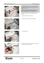
Brand: Fastbind Pages: 4
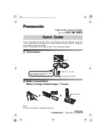
KX-TG9120FX
Brand: Panasonic Pages: 6
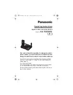
KX-TG8280FX
Brand: Panasonic Pages: 60

Z01
Brand: Hagan Pages: 6

STEAM WIZARD 1000
Brand: Cameo Pages: 30

FI-BP-15N
Brand: Foamit Pages: 10

The Charm
Brand: Gammill Pages: 26

5417C
Brand: Singer Pages: 108

Code-a-phone 700
Brand: Ford Pages: 52

Galaxy Pro 2700-WX-HR
Brand: Edic Pages: 24

BD 44 180
Brand: Kärcher Pages: 54

FURY 1500DCP
Brand: Pacific Pages: 8

HCS2-1201
Brand: Happy Pages: 15

IF 4125
Brand: Sagem Pages: 2

Fax-Lab 480
Brand: Olivetti Pages: 64

INNOVATECH P550Y
Brand: Bartell Pages: 20


