


6-76
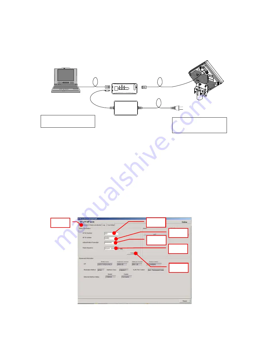
6.3. Connecting the WT Local Management Tool
Connect the WT local management tool terminal to the PC port of the WT adapter (Figure 6-2)
using a straight Ethernet cable.
Figure 6-2 Connection
6.4. WT Local management tool
6.4.1. Configure the WT
Use the WT Local Management Tool to specify the Setup Parameters.
Step 1: Select the Setup tab.
Step 2: Set the WT ID number.
Step 3: Set the AP ID number.
Step 4: Set the authentication parameter.
Step 5: Set the radio frequency.
Step 6: Click the
Setup
button.
Figure 6-3 Configure the WT
IP address: 192.168.1.200
Subnet mask: 255.255.255.0
WT adapter
AC Adapter
AC100〜240V
DC24V
local management tool(PC)
Ethernet cable (Straight)
initial values
IP address:192.168.1.100
Subnet mask:255.255.255.0
Step 1
Step 2
Step 3
Step 4
Step 5
Step 6
Summary of Contents for NT337-XL2
Page 1: ...0 JRC FWA SYSTEM INSTRUCTION MANUAL Rev 3 4 24 SEP 2008...
Page 34: ...2 11 2 2 1 2 AP RFU Omni Antenna Mounting Bracket in mm Figure 2 3 Mounting Bracket...
Page 37: ...2 14 2 2 2 2 AP RFU Sectoral Horn Antenna Mounting Bracket in mm Figure 2 6 Mounting Bracket...
Page 38: ...2 15 2 2 3 AP IFU in mm Figure 2 7 External View of the AP IFU a...
Page 39: ...2 16 2 2 3 1 AP IFU Nameplate Nameplate a in mm Figure 2 8 Nameplate 1 Blank non RoHS R RoHS 1...
Page 40: ...2 17 2 2 4 WT in mm Figure 2 9 External View of the WT 60 a b c 61 190 190 d...
Page 43: ...2 20 2 2 5 WT External Antenna Figure 2 12 External View of the WT External Antenna...
Page 137: ...7 114 Figure 7 2 Configure the WT master Step1 Step4 Step3 Step2 Step5 Step6...
Page 187: ...11 164 JRC FWA SYSTEM Instruction Manual H 7YZCM0101B Rev 3 4 24 SEP 2008...


