8
─
34
8
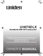
CODE Input
Only for “Service Egineer”
Press “0” and “ENT”
to Adjust Menu
1
2
3
4
5
6
7
8
9
+
0
-
CLR
ENT
8.5
ADJUSTMENTS
This section describes the electrical adjustments of the equipment as the adjustment procedures to be carried
out by service persons at the time of installation.
CAUTION
Do not carry out the adjustments of the equipment
except authorized service persons. If wrong
setting is carried out, this may cause unstable
operation.
Do not carry out the adjustments during
navigation. Otherwise, the radar performance
may be affected, resulting in an accident or
trouble.
Tuning, bearing and range adjustments can be made from the
operation panel. Start the adjustment mode in the following
procedures.
How to open the Adjust Menu
Procedures
1 Continue to press [RADAR MENU] key.
The Code Input Menu will appear.
2 Press [0] key.
3 Move the cursor onto the “ENT”
button in the Code Input menu, and
press [ENT] key.
The Adjust Menu will appear.
Summary of Contents for JMA-5206
Page 2: ......
Page 28: ...xxii ...
Page 30: ...xxiv ...
Page 31: ... xxv Environ mental Protection ENVIRONMENTAL PROTECTION ...
Page 32: ...xxvi ...
Page 39: ...1 6 1 4 EXTERIOR DRAWINGS y 1 Fig 1 1 Exterior Drawing of Scanner Unit Type NKE 2062 HS ...
Page 40: ...1 7 Fig 1 2 Exterior Drawing of Scanner Unit Type NKE 2102 4 ...
Page 41: ...1 8 1 4 EXTERIOR DRAWINGS y 1 Fig 1 3 Exterior Drawing of Scanner Unit Type NKE 2102 6 ...
Page 42: ...1 9 Fig 1 4 Exterior Drawing of Scanner Unit Type NKE 2252 7 ...
Page 43: ...1 10 1 4 EXTERIOR DRAWINGS y 1 Fig 1 5 Exterior Drawing of Scanner Unit Type NKE 2252 9 ...
Page 44: ...1 11 Fig 1 6 Exterior Drawing of Monitor Unit Type NWZ 164 ...
Page 45: ...1 12 1 4 EXTERIOR DRAWINGS y 1 Fig 1 7 Exterior Drawing of Processor Unit Type NDC 1340 ...
Page 46: ...1 13 Fig 1 8 Exterior Drawing of Keyboard Unit Type NCE 7699 ...
Page 47: ...1 14 1 4 EXTERIOR DRAWINGS y 1 Fig 1 9 Exterior Drawing of NSK Unit Type NCT 4106 ...
Page 52: ...1 19 ...
Page 68: ...2 15 ...
Page 218: ...4 7 ...
Page 280: ...5 61 ...
Page 292: ...6 11 ...
Page 345: ...8 44 8 5 Adjustments yyyy yyyy 8 Exit 1 Press RADAR MENU key The Main Menu will reappear ...
Page 402: ...8 101 ...
Page 403: ...SECTION 9 AFTER SALES SERVICE ...
Page 406: ...9 3 ...
Page 430: ...11 19 ...
Page 438: ...Figure 7 Key board unit NCE 7699 Inter connection Diagram ...
Page 439: ...APPENDIX Figure 8 JMA 5200 On screen controls ...
Page 456: ......
Page 458: ...1 ...
Page 460: ...3 ...
Page 461: ......