8
─
88
8.6 Setting
yyyy
yyyy
8
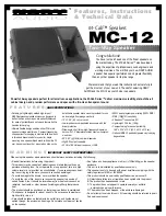
WAAS Setting
1. Mode
AUTO
0. EXIT
2. Ranging
6. Send Data
ON
3. NG WAAS
NOT USE
4. WAAS Select Mode
AUTO
5. WAAS No.
120
Setting in WAAS Receiver (WAAS Setting)
Make settings in the WAAS receiver (our WAAS receiver).
Because the information the WAAS receiver receives from the satellite also includes the same information as
that from DGPS Beacon station, it can perform positioning with higher precision than GPS.
[I]
WAAS Mode Setting (Mode)
Set whether or not differential information of the WAAS receiver is acquired from the Beacon or satellite.
Procedures
1 Press [RADAR MENU] key twice.
The Radar Menu will appear.
2 Press [7] key.
NAV Equipment Setting Menu will appear.
3 Press [7] key.
GPS Setting Menu will appear.
4 Press [3] key.
WAAS Setting Menu will appear.
5 Press [1] key.
From the pull-down menu, select the
following:
BEACON,
WAAS, or
AUTO.
6 After having made entry, press [6]
key to transmit the setting contents
to the WAAS receiver.
Exit
1 Press [RADAR MENU] key.
The Main Menu will reappear.
Summary of Contents for JMA-5206
Page 2: ......
Page 28: ...xxii ...
Page 30: ...xxiv ...
Page 31: ... xxv Environ mental Protection ENVIRONMENTAL PROTECTION ...
Page 32: ...xxvi ...
Page 39: ...1 6 1 4 EXTERIOR DRAWINGS y 1 Fig 1 1 Exterior Drawing of Scanner Unit Type NKE 2062 HS ...
Page 40: ...1 7 Fig 1 2 Exterior Drawing of Scanner Unit Type NKE 2102 4 ...
Page 41: ...1 8 1 4 EXTERIOR DRAWINGS y 1 Fig 1 3 Exterior Drawing of Scanner Unit Type NKE 2102 6 ...
Page 42: ...1 9 Fig 1 4 Exterior Drawing of Scanner Unit Type NKE 2252 7 ...
Page 43: ...1 10 1 4 EXTERIOR DRAWINGS y 1 Fig 1 5 Exterior Drawing of Scanner Unit Type NKE 2252 9 ...
Page 44: ...1 11 Fig 1 6 Exterior Drawing of Monitor Unit Type NWZ 164 ...
Page 45: ...1 12 1 4 EXTERIOR DRAWINGS y 1 Fig 1 7 Exterior Drawing of Processor Unit Type NDC 1340 ...
Page 46: ...1 13 Fig 1 8 Exterior Drawing of Keyboard Unit Type NCE 7699 ...
Page 47: ...1 14 1 4 EXTERIOR DRAWINGS y 1 Fig 1 9 Exterior Drawing of NSK Unit Type NCT 4106 ...
Page 52: ...1 19 ...
Page 68: ...2 15 ...
Page 218: ...4 7 ...
Page 280: ...5 61 ...
Page 292: ...6 11 ...
Page 345: ...8 44 8 5 Adjustments yyyy yyyy 8 Exit 1 Press RADAR MENU key The Main Menu will reappear ...
Page 402: ...8 101 ...
Page 403: ...SECTION 9 AFTER SALES SERVICE ...
Page 406: ...9 3 ...
Page 430: ...11 19 ...
Page 438: ...Figure 7 Key board unit NCE 7699 Inter connection Diagram ...
Page 439: ...APPENDIX Figure 8 JMA 5200 On screen controls ...
Page 456: ......
Page 458: ...1 ...
Page 460: ...3 ...
Page 461: ......