


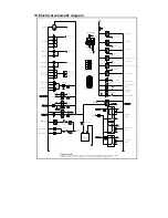


15. Electrical schematic diagram
+
-
Master switch
Spot light signal
Battery
IGN 2
M
Start motor
ST
Dipping switch 2
High beam switch 2
Spot light switch 2
Spot light switch 2
Dipping beam
switch
High beam
switch
Dipping switch 2
High beam switch 1
High beam switch 2
Dipping switch 1
High beam indication
Dipping beam
indication
High beam switch 3
High beam switch 3
Brakes light R
Brakes light L
Fuse 5A
Brakes light switch
Fuse 5A
Horn button
Horn
button
IGN 1
Wire's colour symbol
RS---red/grey B---black R---red U---blue RU---red/blue P---purple S---grey W---white YG---yellow/green L---Cambridge blue N---brown K---pink NB---brown/black NR---brown/red
UW---blue/white RB---red/black GY---green/yellow SB---grey/black BR---black/red Y---yellow WG---white/green GB---green/black WR---white/red BW---black/white
I/p wiring conn 23
I/p wiring conn 30
Reverse light switch
IGN 1
interface flag 2
Head light relay
interface flag 2
Fuse 5A
IGN 1
Fuse 15A
interface flag 2
Spot light switch 1
High beam R
High beam L
Dipping switch 1
dipped beam R
dipped beam L
Clearance lamp
side light *4
T u r n i n g s i g n a l
R * 2
T u r n i n g s i g n a l
L * 2
Turn signal
switch
scintillator
Fuse 5A
spot light*4
G
M
Fuse 15A
Fuel pump relay
Fuel pump
Fuse 15A
Fan relay
Cooling fan
interface flag 1
interface flag 1
Fuse 20A
Main relay
Power for ECU
Body wiring conn 67
Body wiring conn 82
I/p wiring conn
Body wiring conn 69
Body wiring conn 82
Ignition switc
h
Battery
ST
IGN 1
IGN 2
ING 2
Fuse 7.5A
Speed meter
Tachometer
Fuel meter
Oil pressure guage
Speed sensor
Water temperauter meter
Voltage meter
I/p wiring conn 21
Fuelsensor
oil pressure switch
oil pressure
sensor
oil pressure
warning
water temperatuer
warning
Charge indicator
Body wiring conn 28
water temperture Swich
Reverserwarning
Fuse 7.5A
Spot light switch 1
Spot light
switch
High beam switch 1
Summary of Contents for JNSZ1100SVB
Page 6: ...Warranty policy...
Page 7: ......
Page 8: ......
Page 9: ......
Page 10: ......
Page 11: ......
Page 12: ......
Page 13: ......
Page 14: ......
Page 15: ......
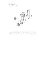
Page 41: ...13 ENGINE WIRING DIAGRAM...
Page 96: ...95 46 ELECTRIC INJECTION SYSTE...
Page 97: ...96...
Page 98: ...97...
Page 99: ...98...
Page 100: ...99...
Page 101: ...100...
Page 102: ...101...
Page 103: ...102...
Page 104: ...103...
Page 105: ...104...
Page 106: ...105...
Page 107: ...106...
Page 108: ...107...
Page 109: ...108...
Page 110: ...109...
Page 111: ...110...
Page 112: ...111...
Page 113: ...112...
Page 114: ...113...
Page 115: ...114...
Page 116: ...115...
Page 117: ...116...
Page 118: ...117...
Page 119: ...118...
Page 120: ...119...
Page 121: ...120...
Page 122: ...121...
Page 123: ...122...
Page 124: ...123...
Page 125: ...124...
Page 126: ...125...
Page 127: ...126...
Page 128: ...127...
Page 129: ...128...
Page 130: ...129...
Page 131: ...130...
Page 132: ...131...
Page 133: ...132...
Page 134: ...133...
Page 135: ...134...
Page 136: ...135...
Page 137: ...136...
Page 138: ...137...
Page 218: ...217 4 Attach tie rod and front wheel...
Page 225: ...224 DEALER PRE DELIVERY INSPECTION...