background image

3

JO

NIX

VMC

TABLE OF CONTENTS

1 - GENERAL INFORMATION

5

1.1 - SERIAL NUMBER PLATE

5

1.2 - LIABILITY

5

1.3 - SYMBOLS

6

2 - WARNINGS AND GENERAL PROHIBITIONS

6

3 - THE OPERATING SYSTEM

8

4 - TECHNICAL DATA 

JO

NIX


VMC

9

4.1 - COMPONENT DESCRIPTION 

JO

NIX


VMC

9

4.1.1 - Technical features 

JO

NIX


VMC

9

4.2 - SPARE PARTS AVAILABLE ON ORDER 

JO

NIX


VMC

9

5 - RECEPTION, TRANSPORT AND STORAGE

10

5.1 - PACKAGING

10

5.2 - HANDLING AND TRANSPORT

10

5.3 - INSPECTION UPON RECEPTION

10

5.4 - STORAGE

10

5.5 - HANDLING DEVICE IN OPERATING CONDITIONS

10

6 - INSTALLATION AND COMMISSIONING

11

6.1 - SAFETY STANDARDS

11

6.2 - GETTING STARTED

12

6.3 - CHOOSING THE INSTALLATION SITE

12

6.4 - INSTALLING THE DEVICE

13

6.5 - ELECTRICAL CONNECTIONS

14

6.6 - ELECTRIC POWER SUPPLY

14

6.7 - USING THE DEVICE

15

7 - MAINTENANCE

18

7.1 - WARNINGS

18

7.2 - ROUTINE MAINTENANCE

18

7.2.1 - Cleaning the Ionising Tubes

19

7.2.2 - External cleaning of the equipment

21

7.3 - SPECIAL MAINTENANCE

22

7.3.1 - Replacing the Ionising Tubes

22

8 - OPERATIONAL CHECK AND TROUBLESHOOTING

24

9 - DISPOSAL

25

WARRANTY CONDITIONS

26

EC DECLARATION OF CONFORMITY

27

ATTACHMENTS

28

OVERALL DIMENSIONS 

JO

NIX


VMC

28

ELECTRICAL DIAGRAMS 

JO

NIX


VMC

29

Summary of Contents for 70MICVMC2C

Page 1: ...MADE IN ITALY JONIX VMC DUCTABLE IONISING MODULE USE AND MAINTENANCE MANUAL...

Page 2: ...ONIX srl reserves every right concerning this manual including the right to make any necessary change or improvement to its products and to the manual at any time and without notice It is forbidden to...

Page 3: ...G DEVICE IN OPERATING CONDITIONS 10 6 INSTALLATION AND COMMISSIONING 11 6 1 SAFETY STANDARDS 11 6 2 GETTING STARTED 12 6 3 CHOOSING THE INSTALLATION SITE 12 6 4 INSTALLING THE DEVICE 13 6 5 ELECTRICAL...

Page 4: ...t damage caused by incorrect installation or damage caused by the units installed by inexperienced and or unauthorised staff At the time of purchase check that the device is intact and complete The Ma...

Page 5: ...ctly forbidden to use the device in environments where the air is mixed with and or altered by other gaseous compounds and or solid particles Using the device for purposes other than those intended an...

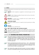
Page 6: ...that sold you the device 2 WARNINGS AND GENERAL PROHIBITIONS HAZARD It refers to dangerous situations that may result from the use of the device in order to ensure personal safety WARNING It refers t...

Page 7: ...the device Please note that the use of products that require electricity involves the observance of some crucial safety rules such as When installing commissioning and operating this product it is ma...

Page 8: ...es of JONIX VMC are High efficiency reduction of bioburden and of volatile organic compounds up to 99 compared to the initial concentration Low power consumption from 20 to 40 VA Strong deodorizing ac...

Page 9: ...CRIPTION JONIX VMC 4 1 1 Technical features JONIX VMC As a result it is easy to implement a software interface capable of displaying messages requesting maintenance when this signal is received The th...

Page 10: ...Any damage must be reported to the carrier by filling in the relevant section on the delivery note and specifying the type of damage 5 3 INSPECTION UPON RECEPTION The Manufacturer disclaims any liabi...

Page 11: ...of the various components and of the electrical mains to which it is connected making sure that it is fitted with a circuit breaker upstream of the power line as shown in this manual Never insert obj...

Page 12: ...ntained in this manual Never force the components when assembling although it is made with high strength materials the parts of the device can be damaged if handled incorrectly Do not try to perform m...

Page 13: ...t be carried out following the instructions provided in this manual Make sure that voltage and frequency of the electric line correspond to those provided on the name plate The electrical mains of the...

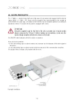
Page 14: ...The ON OFF switch indicates when the device is powered ATTENTION Using the supplied rope for the link to the net or provide one of equal section always composed by F N and T Before making any connect...

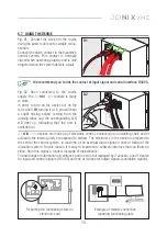
Page 15: ...nd you to link the contact of input signal and serial interface RS485 JONIX VMC devices are made up of electronic control enclosed in an insulating shell and of actuators the ionising unity are expose...

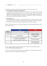
Page 16: ...in HV generators gets out from a defined range Once done the requested operations the relay can be reset through a commmand on serial line or through IN1 entrance In this last case you have to appluy...

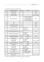
Page 17: ...ure 9 Threshold MAX voltage generators cV Lecture 10 Alarm MAX voltage generators 0 not active 1 active type 0 to reset Lecture Scripture 11 Count hours maintenance Hours Hours Lecture 12 Threshold co...

Page 18: ...formed to ensure proper maintenance of the device JONIX VMC depends mainly on the quality of the treated air Air can be especially harmful for condensers when it contains polluting or aggressive subst...

Page 19: ...the outer mesh from the tube if you have not already done so in the previous point Clean the glass using a damp cloth If the operation is difficult to perform pull slightly the earthing spring so that...

Page 20: ...nsure a minimum distance of at least 3 mm from the base of the tube Fig 09 Gently screw the ionising tube holding on to the base green part If the operation is difficult to perform pull slightly the e...

Page 21: ...te sockets of the JONIX VMC module Switch on the moduleby turning the On Off switch to I Verify the functioning of the device it has to be hear a light sizzle coming from the tubes Reset the alarm rep...

Page 22: ...t after 14000 hours of operation 7 3 SPECIAL MAINTENANCE 7 2 1 Replacing the Ionising Tubes Fig 12 Switch off the ionising module JONIX VMC by turning the luminous On Off switch to O Remove the plug c...

Page 23: ...rer Fig 16 Reposition the device JONIX VMC by inserting the ionising tubes horizontally into the specific hole and screw the 2 screws that secure the module to the wall Fig 17 Reinsert the power suppl...

Page 24: ...tioning and the spy is on The red led of the internal electronic card emits an intermittent flashing The system detects the need of cleaning the ionising tube Follow the cleaning of the ionising tubes...

Page 25: ...hrough your municipal authorities as to the location of the eco friendly waste management sites where waste can be received for disposal and its subsequent recycling as recommended Furthermore please...

Page 26: ...tems that are damaged or faulty due to replacement of components or accessories with others of a type that is not explicitly approved by the manufacturer interventions carried out by unauthorised or u...

Page 27: ...S o Duct o DuctR VMC Select the model to which the declaration refers to product code xxx serial n xxx E CONFORME F U L F I L S 2011 65 EU ROHS Directive 2014 30 EU EMC Directive ex 2004 108 EC 2014 3...

Page 28: ...28 JONIXVMC 160 200 280 90 190 5 5 5 5 80 80 33 8 3 5 2 163 134 2 5 2 5 188 5 8 8 67 10 5 10 5 24 24 ATTACHMENTS OVERALL DIMENSIONS JONIX VMC 70MICVMC2C...

Page 29: ...ELECTRICAL DIAGRAMS JONIX VMC 70MICVMC2C...

Page 30: ...YPE MIN SUGGEST CROSS SECTION LINE mm VS MAX LENGTH m AIR TEMPERATURE 30 C MULTICORE CABLE CABLE INSIDE TUBE ON AIR PVC INSULATED EPR G7 G10 INSULATED CABLE WORKING TEMPERATURE 70 C MAX LENGHT VOLTAGE...

Page 31: ......

Page 32: ......

Page 33: ......

Page 34: ......

Page 35: ......

Page 36: ......

Page 37: ......

Page 38: ......

Page 39: ......

Page 40: ...33 35020 Tribano PD Italy tel 39 049 9588511 fax 39 049 9588522 via Tegulaia 10 b 56121 Pisa Italy tel 39 050 985165 via Romagnoli 12 a 40010 Bentivoglio BO Italy JONIX srl Registered office Scientifi...

Reviews: