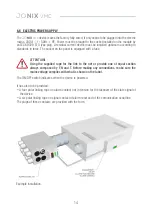
16
JO
NIX
VMC
BLUE
RED
NUMBER
OF FLASH
DESCRIPTION
1
Necessity of periodic.
2
Active ionisation.
Necessity of sostitution
of generators.
3
error equipement (blocked ionisation until the
next reboot) - SHORT-CIRCUIT
(removed power supply to the processor)
Possible presence of short-circuit in
one or more generators.
4
Possible lack/breakup of
one or more generators.
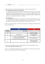
It exists a relay that allows to activate or disactivate the ionisation through Modbus protocol:
3. RL3 (F OUT) Activation Generator of HV.
There is a serial line RS485 with Modbus protocol (4800N81) for the programming of the main
parameters and the remote diagnosis of the equipement.
2. RL2 Broken alarm.
It is enabled if the control voltage in HV generators gets out from a defined range. Once done
the requested operations the relay can be reset through a commmand on serial line or through
IN1 entrance. In this last case you have to appluy a short-circuit of 5 seconds.
Two leds, one red and one blue, in the electronic card inside the module provide indications of the
type of the active alarm.
The alarms are split up into type and marked through 2 clean contact usually opened:
1. RL1 Maintenance alarm periodic/replacement.
It is enabled after 1000 hours of functioning to indicate the necessity of a periodic cleaning
of plasma generators (flashing way 5 sec on, 2 sec off) or after 14000 hours to ask the
sostitution of generators themselves (fixed way)..Once done the requested operations the
relay can be reset through command on serial line or through IN1 entrance. In this last one
case you have to apply a short-circuit of 2 seconds.


