162
JOHNSON CONTROLS
FORM 201.21-NM4 (616)
162
JOHNSON CONTROLS
TECHNICAL DATA
CHILLER ELECTRONIC COMPONENTS (CON'T)
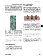
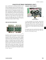
DV/DT OUTPUT SUPPRESSION NETWORK
50083
DV/DT
RESISTORS
DV/DT
CAPACITORS
The dV/dT Output Suppression Network limits the rate
of rise of voltage and the peak voltage of the PWM
pulses applied to the motor windings. This eliminates
the possibility of causing a turn-to-turn short in the motor
due to winding insulation breakdown. The suppression
network is made up of a 3 phase RC network.
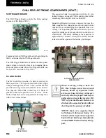
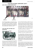
FLASH TANK FEED AND DRAIN VALVE
CONTROLLER
The Flash Tank Feed and Drain Valve Controller is a
microprocessor driven controller that operates the Feed
and Drain Valves based on commands from the Chiller
Control Board. The Feed and Drain Valves control the
level of liquid in the Flash Tank and the superheat to the
evaporator. The controller is a stand-alone valve control
module in the Control/VSD panel. The Flash Tank liquid
level is controlled by sequencing a stepper motor valve
(Feed Valve) on the inlet of the flash tank. The controller
opens and closes the feed valve to control the liquid level
of the refrigerant in the Flash Tank based on commands
from the Chiller Control Board. Superheat is controlled
by sequencing a stepper motor valve (Drain Valve) on
the outlet of the Flash Tank. The controller opens and
closes the drain valve to control flow to the evaporator
and ultimately superheat to the compressor based on
commands from the Chiller Control Board.
Drain Valve superheat control is controlled by a PI
control algorithm based on suction pressure and suction
temperature in the Chiller Control Board software.
The control algorithms will attempt to control the level
in the flash tank to approx 35% when the economizer is
energized. If the level exceeds 87.5%, the system will
fault. The normal 35% level may fluctuate appreciably
when the economizer is off as the Flash Tank acts as
nothing more than a reservoir as the Drain Valve controls
superheat. The level will also vary when the economizer
is first energized or a system transient occurs such as
fan cycling, etc.
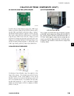
The two controllers are typically located in the back of
the panel behind the power wiring terminal block/circuit
breaker (4 compressor, VC1 &VC2) or on the wall of
the panel on the left side of the cabinet (3 compressor,
VC2) and behind the power wiring terminal block/circuit
breaker (3 compressor VC1).
LD10619

