background image

437642-UIM-C-0210

20

Johnson Controls Unitary Products

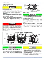
ADJUSTMENT OF MANIFOLD GAS PRESSURE & 

INPUT RATE

Inlet and manifold gas pressure may be measured by connecting the
“U” tube manometer to the gas valve with a piece of tubing. Follow the
appropriate section in the instructions below. Refer to Figure 22 for a
drawing of the locations of the pressure ports on the gas valve.

Turn gas off at the ball valve or gas cock on gas supply line 
before the gas valve. Find the pressure ports on the gas 
valve marked Out P and In P.

1.

The manifold pressure must be taken at the port marked OUT P.

2.

The gas line pressure must be taken at the port marked IN P.

3.

Using a 3/32” (2.4 mm) Allen wrench, loosen the set screw by turn-
ing it 1 turn counter clockwise. DO NOT REMOVE THE SET 
SCREW FROM THE PRESSURE PORT.

Read the inlet gas pressure

Connect the positive side of the manometer to the IN P Tap on the gas 
valve. Do not connect any tubing to the negative side of the manometer, 
as it will reference atmospheric pressure. Refer to Figure 23 for connec-
tion details.

1.

Turn gas and electrical supplies on and follow the operating
instructions to place the unit back in operation.

2.

Once the correct gas inlet pressure has been established, see
Table 11, turn the gas valve to OFF and turn the electrical supply
switch to OFF; then remove the flexible tubing from the gas valve
pressure tap and tighten the pressure tap plug using the 3/32” (2.4
mm) allen wrench.

3.

Turn the electrical and gas supplies back on, and with the burners
in operation, check for gas leakage around the gas valve pressure
port for leakage using an approved non-corrosive gas leak detec-
tion fluid, or other non-flammable leak detection methods.

Read the manifold gas pressure

Connect the positive side of the manometer to the adapter previously
installed in the OUT P Tap on the gas valve. Do not connect any tubing
to the negative side of the manometer, as it will reference atmospheric
pressure. Refer to Figure 23 for connection details.

1.

Refer to Figure 22 for location of pressure regulator adjustment
cap and adjustment screws on main gas valve.

2.

Turn gas and electrical supplies on and follow the operating
instructions to place the unit back in operation.

3.

Adjust manifold pressure by adjusting gas valve regulator screw
for the appropriate gas per the following:

4.

After the manifold pressure has been adjusted, re-calculate the
furnace input to make sure you have not exceeded the specified
input on the rating plate. Refer to “CALCULATING THE FURNACE
INPUT (NATURAL GAS)”.

5.

Once the correct BTU (kW) input has been established, turn the
gas valve to OFF and turn the electrical supply switch to OFF; then
remove the flexible tubing from the gas valve pressure tap and
tighten the pressure tap plug using the 3/32” (2.4 mm) Allen
wrench.

6.

Turn the electrical and gas supplies back on, and with the burners
in operation, check for gas leakage around the gas valve pressure
port for leakage using an approved non-corrosive gas leak detec-
tion fluid, or other non-flammable leak detection methods.

Table 11: 

Inlet Gas Pressure Range

INLET GAS PRESSURE RANGE

Natural Gas

Propane (LP)

Minimum*

4.5” w.c. (1.12 kPa)

8.0” w.c. (1.99 kPa)

Maximum

10.5” w.c. (2.61 kPa)

13.0” w.c. (3.24 kPa)

The inlet gas pressure operating range table specifies what the
minimum and maximum gas line pressures must be for the furnace
to operate safely. The gas line pressure MUST BE a minimum of:

7” w.c. (1.74 kPA) for Natural Gas

11” w.c. (2.74 kPA) for Propane (LP) Gas

in order to obtain the BTU input specified on the rating plate and/or
the nominal manifold pressure specified in these instructions and
on the rating plate.

The cap for the pressure regulator must be removed to gain access
to the adjustment screw. Loosening or tightening the cap does not
adjust the flow of gas.

The regulated outlet pressures, both low and high, have been cali-
brated at the factory. Additional pressure adjustment should not be
necessary. If adjustment is necessary, set to the following specifica-
tions. After adjustment, check for gas leakage.

Table 12: 

Nominal Manifold Pressure

NOMINAL MANIFOLD PRESSURE

Natural Gas

3.5" w.c. (0.87 kPa)

Propane (LP) Gas

10.0" w.c. (2.488 kPa)

 FIGURE 22:  

Gas Valve

If gas valve regulator is turned in (clockwise), manifold pressure is
increased. If screw is turned out (counter clockwise), manifold pres-
sure will decrease.

NOTICE

INLET

WRENCH
BOSS

INLET
PRESSURE
PORT

ON

OFF

ON/OFF SWITCH
(Shown in ON position)

MAIN REGULATOR
ADJUSTMENT

OUTLET

OUTLET
PRESSURE
PORT

VENT PORT

Summary of Contents for TM8X*MP Series

Page 1: ...Return 22 Blower Performance CFM Any Position without filter Left Side Return 23 These high efficiency compact units employ induced combustion reli able hot surface ignition and high heat transfer alu...

Page 2: ...abinet support the ends of the furnace rather than lifting by the cabinet flanges at the return air openings bottom or sides or supply air opening 13 When lifting the furnace it is acceptable to use t...

Page 3: ...the National Fire Protection Association Inc Batterymarch Park Quincy MA 02269 or for only the NFGC contact the American Gas Association 400 N Capital N W Washington DC 20001 or www NFPA org CANADA NS...

Page 4: ...xide detector with an alarm and battery back up is installed on the floor level where the gas equipment is to be installed In addition the installing plumber or gasfitter shall observe that a battery...

Page 5: ...access cover shall be attached in such a manner as to prevent leaks DUCT FLANGES Four flanges are provided to attach ductwork to the furnace These flanges are rotated down for shipment In order to use...

Page 6: ...uld always be installed on the side desig nated as top side See Figures 4 5 FURNACE ASSEMBLY PC SERIES COILS These upflow coils are designed for installation on top of upflow fur naces only If the coi...

Page 7: ...e unit BOTTOM RETURN AND ATTIC INSTALLATIONS Bottom return applications normally pull return air through a base plat form or return air plenum Be sure the return platform structure or return air plenu...

Page 8: ...15 2 cm minimum clearance between the front of the furnace and the support rods or straps All six suspension points must be level to ensure proper and quiet fur nace operation When suspending the fur...

Page 9: ...stat Wiring FRONT 14 1 1 5 23 SUPPLY END C 24 38 20 5 B Gas Pipe Entry Thermostat Wiring 33 A 5 Electrical Entry Vent Connection Outlet Vent Connection Outlet 4 Diameter Outlet Vent Connection Table 3...

Page 10: ...r side of the furnace using any of the gas pipe entry on both sides of the furnace Refer to Figure 12 All filters and mounting provision must be field supplied All installa tions must have a filter in...

Page 11: ...0 87 0 87 0 81 1000 3 5 3 2 2 9 37 3 0 87 0 80 0 73 1050 3 5 2 9 2 7 39 1 0 87 0 73 0 67 1100 3 2 2 7 2 4 41 0 0 80 0 66 0 61 2500 LP 9 8 8 2 7 5 93 2 LP 2 44 2 03 1 86 PROPANE AND HIGH ALTITUDE CONVE...

Page 12: ...to power auxiliary devices such as humidifiers air cleaners etc The transformer may provide power for an air conditioning unit contactor ACCESSORY CONNECTIONS The furnace control will allow power swi...

Page 13: ...with Hi Efficiency Motor HM1 Humidistat Y Full Stage Compressor G Fan PP11C70224 THERMOSTAT RH 24 Volt Hot Heat XFMR RC 24 Volt Hot Cool XFMR W Full Stage Heat Clipping Jumper W914 for electric heat...

Page 14: ...t Numbers SAP Legacy 67297 031 01975 E B E ZD E R OD MODELS HGD HP RHS O Reversing Valve Energized in Cool C 24 Volt Common R 24 Volt Hot W1 66 out Heat Y Compressor DEMAND DEFROST CONTROL X L Malfunc...

Page 15: ...mney must extend at least 5 ft 1 5 m above the highest equipment draft hood or flue collar FAN ASSISTED COMBUSTION SYSTEM This appliance is equipped with an integral mechanical means to either draw pr...

Page 16: ...free area Ventilated Combustion Air The ventilated attic space or a crawl space from which the combustion air is taken must comply with the requirements specified in AIR SOURCE FROM OUTDOORS in this i...

Page 17: ...other appliances connected to the venting system are not in operation 1 Inspect the venting system for proper size and horizontal pitch Determine that there is no blockage restriction leakage corrosio...

Page 18: ...non corrosive leak detection fluid or other leak detection methods Take appropriate steps to stop any leak If a leak persists replace the component CALCULATING THE FURNACE INPUT NATURAL GAS Verify na...

Page 19: ...22 164 327 818 64 56 112 281 23 157 313 783 66 54 109 273 24 150 300 750 68 53 106 265 25 144 288 720 70 51 103 257 26 138 277 692 72 50 100 250 27 133 267 667 74 48 97 243 28 129 257 643 76 47 95 23...

Page 20: ...n and follow the operating instructions to place the unit back in operation 3 Adjust manifold pressure by adjusting gas valve regulator screw for the appropriate gas per the following 4 After the mani...

Page 21: ...must be long enough to adequately cool the furnace but not so long that cold air is blown into the heated space The fan off timing may be adjusted by positioning the jumper on two of the four pins as...

Page 22: ...638 2540 2448 2339 2224 2111 1974 1831 Medium High 2234 2233 2147 2092 2042 1974 1907 1820 1705 1575 Medium Low 1722 1716 1690 1681 1603 1553 1489 1426 1335 1241 Low 1396 1375 1348 1325 1263 1200 1150...

Page 23: ...ow 1126 1115 1095 1049 1027 996 957 929 840 742 080C22 High 2972 2863 2769 2671 2571 2465 2352 2227 2095 1950 Medium High 2173 2146 2103 2082 2036 1966 1904 1827 1738 1621 Medium Low 1670 1667 1647 16...

Page 24: ...HI COOL speed when Y1 and Y2 are energized Heating Cycle When the thermostat switch is set on HEAT and the fan is set on AUTO and there is a call for heat a circuit is completed between terminals R a...

Page 25: ...pressure switch hose or faulty pressure switch 4 RED FLASHES This indicates that the main limit switch has opened its normally closed contacts The control will operate the supply air blower and induce...

Page 26: ...L Models Only MISCELLANEOUS ORIFICE BURNER Natural 45 SIGHT GLASS OVAL 2 Req d GASKET FOAM Door 1 5 ft req d GASKET INTAKE PAN PLUG VENT HOLE BRACKET DOOR WIRING HARNESS FERRULE 3 Req d GROMMET 3 Req...

Page 27: ...437642 UIM C 0210 Johnson Controls Unitary Products 27 SECTION X WIRING DIAGRAM FIGURE 25 Wiring Diagram...

Page 28: ...hange without notice Published in U S A 437642 UIM C 0210 Copyright 2010 by Johnson Controls Inc All rights reserved Supersedes 437642 UIM B 0109 Johnson Controls Unitary Products 5005 York Drive Norm...

Reviews: