


437642-UIM-C-0210
16
Johnson Controls Unitary Products
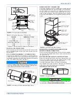
Air Supply Openings and Ducts
1.
An opening may be used in lieu of a duct to provide the outside air
supply to an appliance unless otherwise permitted by the authority
having jurisdiction. The opening shall be located within 12” (30.5
cm) horizontally from, the burner level of the appliance. Refer to
“COMBUSTION AIR SOURCE FROM OUTDOORS and VENT
AND SUPPLY AIR SAFETY CHECK” in these instructions for
additional information and safety check procedure.
2.
The duct shall be either metal, or a material meeting the class 1
requirements of CAN4-S110 Standard for Air Ducts.
3.
The duct shall be least the same cross-sectional area as the free
area of the air supply inlet opening to which it connects.
4.
The duct shall terminate within 12” (30.5 cm) above, and within 24”
(61 cm) horizontally from, the burner level of the appliance having
the largest input.
5.
A square or rectangular shaped duct shall only be used when the
required free area of the supply opening is 9 in
2
(58.06 cm
2
) or
larger. When a square or rectangular duct is used, its small dimen-
sion shall not be less than 3” (7.6 cm).
6.
An air inlet supply from outdoors shall be equipped with a means
to prevent the direct entry of rain and wind. Such means shall not
reduce the required free area of the air supply opening.
7.
An air supply inlet opening from the outdoors shall be located not
less than 12” (30.5 cm) above the outside grade level.
Combustion Air Source from Outdoors
1.
Two permanent openings, one within 12” (30.5 mm) of the top and
one within 12” (30.5 mm) of bottom of the confined space, Two
permanent openings, shall communicate directly or by means of
ducts with the outdoors, crawl spaces or attic spaces.
2.
One permanent openings, commencing within 12” (30.5 cm) of the
top of the enclosure shall be permitted where the equipment has
clearances of at least 1” (2.54 cm) from the sides and back and 6”
(15.24 cm) from the front of the appliance. The opening shall com-
municate directly with the outdoors and shall have a minimum free
area of:
a.
1 square in per 3000 Btu per hour (6.45 cm
3
per 0.879 kW) of
the total input rating of all equipment located in the enclosure.
b.
Not less than the sum of all vent connectors in the confined
space.
3.
The duct shall be least the same cross-sectional area as the free
area of the air supply inlet opening to which it connects.
4.
The blocking effects of louvers, grilles and screens must be given
consideration in calculating free area. If the free area of a specific
louver or grille is not known. Refer to Table 7 to estimate free area.
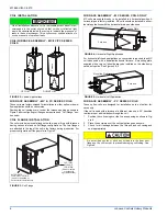
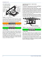
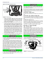
Ventilated Combustion Air
The ventilated attic space or a crawl space from which the combustion
air is taken must comply with the requirements specified in “AIR
SOURCE FROM OUTDOORS” in this instruction or in Section 5.3, Air
for Combustion and Ventilation of the National Fuel Gas Code, ANSI
Z223.1 (latest edition). This type installation requires two properly sized
pipes. One brings combustion air from a properly ventilated attic space
or crawl space and a second pipe that extends from the furnace vent
connection (top right of unit) to the exterior of the building.
Vent and Supply (Outside) Air Safety Check Procedure
For Category I furnaces, vent installations shall be in accordance with
Parts 7 and 11 of the National Fuel Gas Code, ANSI Z223.1/NFPA 54,
and or Section 7 and Appendix B of the CSA B149.1, Natural Gas and
Propane Installation Codes, the local building codes, furnace and vent
manufacture's instructions.
Multi-story or common venting systems are permitted and must be
installed in accordance with the National Fuel Gas Code, ANSI Z223.1/
NFPA 54 and / or the CSA B149.1, Natural Gas and Propane Installa-
tion Codes, local codes, and the manufacture's instructions.
Vent connectors serving Category I furnaces shall not be connected
into any portion of mechanical draft systems operating under positive
pressure.
When a Category I furnace is removed or replaced, the original
venting system may no longer be correctly sized to properly vent
the attached appliances.
An improperly sized vent system can cause CARBON MONOXIDE
to spill into the living space causing personal injury, and or death.
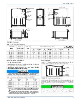
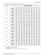
Table 8:
Unconfined Space Minimum Area
BTUH Input Rating
Minimum Free Area
Required for Each Opening
60,000
60 in
2
(387 cm
2
)
80,000
80 in
2
(516 cm
2
)
100,000
100 in
2
(645 cm
2
)
120,000
120 in
2
(742 cm
2
)
Table 9:
Free Area
BTUH Input
Rating
Minimum Free Area Required for Each Opening
Horizontal Duct
(2,000 BTUH)
Vertical Duct or
Opening to Outside
(4,000 BTUH)
Round Duct
(4,000 BTUH)
60,000
30 in
2
(193 cm
2
)
15 in
2
(97 cm
2
)
5” (13 cm)
80,000
40 in
2
(258 cm
2
)
20 in
2
(129 cm
2
)
5” (13 cm)
100,000
50 in
2
(322 cm
2
)
25 in
2
(161 cm
2
)
6” (15 cm)
120,000
60 in
2
(387 cm
2
)
30 in
2
(193 cm
2
)
7” (18 cm)
EXAMPLE: Determining Free Area.
Appliance
1 Appliance
2 Total Input
100,000
+ 30,000 = (130,000
4,000) = 32.5 Sq. In. Vertical
Appliance
1 Appliance
2 Total Input
100,000
+ 30,000 = (130,000
2,000) = 65 Sq. In. Horizontal
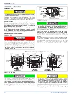
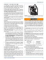
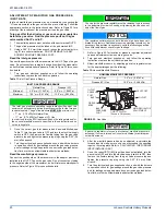
FIGURE 21:
Outside and Ambient Combustion Air
Gable
Vent
Gas
Vent
Soffit
Vent
Ventilated
Attic
Top Above
Insulation
Optional
Inlet (a)
Outlet
Air (a)
Ventilated
Crawl Space
Gas
Water
Heater
Furnace
Soffit
Vent
Gas
Water
Heater
Inlet
Air (a)
Inlet
Air (b)
Furnace
Gas
Vent
Outlet
Air (a)
Outlet
Air (b)
Inlet
Air (a)
Inlet
Air (b)
Gas
Water
Heater
Furnace
Ventilated
Attic
Top Above
Insulation
Gable
Vent
Gas
Vent