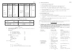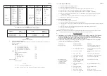
Component
Internal Size
Resistance
Component
Internal Size
Resistance
(mm)
Factor
(mm)
Factor
Flue Blocks
197 x 67
0.85 per meter
135
O
Bend
100 mm pipe
0.61 per
231 x 65
0.65 run
125 mm pipe
0.25 fitting
317 x 63
0.35
150 mm pipe
0.12
140 x 102
0.60
197 x 67
0.30
200 x 75
0.60
231 x 65
0.22
183 x 90
0.45
317 x 63
0.13
Pipe
100
0.78
Raking block
Any
0.30 per block
125
0.25
150
0.12
Adaptor block
Any
0.50
Chimney
213 x 213
0.02
Terminal
100 mm ridge
2.5
125 mm ridge
1.0
90
O
Bend
100 mm pipe
1.22 per
150 mm ridge
0.48
125 mm pipe
0.50 fitting
100 mm GCI
0.6
150 mm pipe
0.24
125 mm GCI
0.25
150 mm GCI
0.12
Table 3
Resistance factors for use in calculating equivalent heights
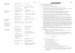
Appliance
Inlet
Flue
Outlet
Resistance (K
i
)
Resistance (K
o
)
100 mm dia spigot
2.5
100 mm flue
2.5
125 mm dia spigot
1.0
125 mm flue
1.0
150 mm dia spigot
0.48
150 mm flue
0.48
Table 4
Inlet and outlet resistance
d.
Worked Calculation Example:
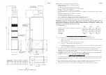
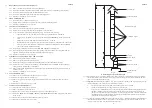
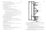
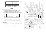
A warm air unit with a 100 mm diameter flue spigot, fitted with a pre-fabricated flue system leading to a
ridge tile (refer Fig. 2):
From table 4:
K
ia
Inlet resistance of actual flue
= 2.5
K
oa
Outlet resistance of actual flue
= 2.5
K
ie
Inlet resistance of equivalent flue
= 2.5
K
oe
Outlet resistance of the actual flue
= 2.5
From table 3:
Other resistances of actual flue:
Terminal
= 2.5
Pipe bend ( 2 x 0.61)
= 1.22
Pipe (4 x 1m @ 0.78)
= 3.12
(5 x 0.3m @ 0.78)
= 1.17
Sum K
= 8.01
Equivalent height :
From the formula
(2.5 + 2.5)
H
e
= 6.2 x ______________________
(2.5 + 2.5) - (0.78 x 6.2) + 8.01
H
e
= 3.793
This flue exceeds 1.0m equivalent height and is therefore satisfactory.
5
ZZ602/6
ZZ602/6
14
8.12
LIMIT SWITCH REMOVAL:
8.12.1 Ensure that the electrical supply is isolated.
8.12.2 Remove the appliance central front door.
8.12.3 Disconnect the 2 BLUE conductors from the Interrupter at the Multifunctional Control.
8.12.4 Release the 2 x screws securing the Fan Delay Control cover, and withdraw the cover.
8.12.5 Release the 2 x screws securing the Temperature Probe assembly, and withdraw the assembly.
8.12.6 Remove the Temperature Probe from the terry clip, and withdraw the probe from the assembly having first
removed the grommet.
8.12.7 Release the 2 x screws securing the Limit Switch, and withdraw the control from the appliance.
8.12.8 Refitment or replacement is in reverse order.
8.13
HEAT EXCHANGER ACCESS:
8.13.1 Remove the upper and central front doors.
8.13.2 Remove the Burner and Controls assembly as detailed in para 8.2
8.13.3 Release the 4 x securing screws and remove heat exchanger access plate and gasket from the front of the draught
diverter.
8.13.4 Release the nuts securing the baffle retaining plate, and remove the retaining plate and washers.
8.13.5 Remove the heat exchanger baffles.
8.13.6 Reassembly is in reverse order.
NOTE:
When reassembling, ensure that the baffle is pushed fully home and access cap is fully sealed. In the event of heat
exchanger replacement being necessary, contact Johnson and Starley Service Department.
9.
DEFECT DIAGNOSIS
9.1
IMPORTANT: If an electrical defect occurs after installation of the appliance; preliminary earth continuity,
polarity, and resistance to earth checks should be carried out with a multimeter. On completion of any
maintenance/fault-finding task that has required the breaking and remaking of electrical connections, then
checks of continuity, polarity, and resistance to earth must be repeated.
9.2
WARNING:
When purging or checking gas supplies, ensure that the ventilation to the room or cupboard is
adequate, and that all naked lights are extinguished.
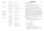
SYMPTOM
POSSIBLE CAUSE
REMEDY
a. Pilot will not light.
i.
No gas supply to heater.
Check for gas at inlet pressure test
point on multifunctional control.
ii.
Gas supply pipe not purged.
Purge gas supply pipe in accordance
with BS 6891.
iii
Pilot orifice restricted.
Clear pilot orifice or replace pilot
injector.
iv.
Piezo system faulty.
Check igniter, lead, and electrode.
v.
Limit Switch has operated
Relight Pilot or replace Limit Switch
vi
Limit Switch connections
Check connections and wiring.
damaged
b. Pilot lights but goes
i.
Connection between thermo-
Check connection is secure.
out on releasing START
couple and Multifunctional
button during initial
Control not secure.
light-up, or after
normal operation.
ii.
Faulty power unit on gas
Replace Multifunctional Control.
control.
iii.
Faulty thermocouple.
Replace Thermocouple.
iv.
Pilot flame too small.
Adjust.
v.
Pilot orifice restricted.
Replace Pilot injector
vi.
Limit control has operated
Relight Pilot or replace Limit Switch.


