background image

5.

INSTALLATION REQUIREMENTS

5.1

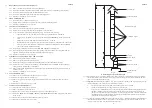
  FLUES (see British Standards BS5440 Pt.1 Flues)

5.1.1

All joints shall be soundly sealed.

5.1.2

The flue should be kept as short and warm as possible.

5.1.3

Sufficient support brackets shall be installed to bear the weight of the total flue system.

5.1.4

The spigot connection of the heater draught diverter will accept internally the spigot end of a non-asbestos flue
to BS567 or twin wall metal flue to BS715 of nominal diameter as specified in para 1.2.

5.1.5

A split collar should be fitted to provide for flue maintenance or inspection.

5.1.6

The flue shall be in accordance with the Building Regulations and British Gas Materials and  Installations
specification 3rd edition) with regard to clearance and shielding from combustible materials.

5.1.7

All materials shall be in accordance with local gas region and Building Regulations requirements.

5.1.8

The flue should run as vertically as possible. Horizontal runs should be avoided if at all possible and any
directional change should be as gentle as possible. If there is any doubt about the flue configuration, the
equivalent flue height should be determined (see 5.1.10).

5.1.9

If the appliance to be fitted is a replacement, the old appliance should be checked for signs of spillage prior to
commencement of the installation and appropriate action taken, (i.e. check flue system and renew as necessary).

5.1.10 It is recommended that at least 600mm of vertical flue should be provided from the top of the draught diverter

(for new installations this shall be incorporated into the flue design). However, when carrying out replacement
installations, an existing flue system may be encountered, where the vertical flue above the appliance to the first
bend is less than 600mm. In the first instance, the installer must judge whether this distance can be achieved
practicably by some means. Where this is not practicable, the existing flue system may be used, providing there is
no evidence of spillage from the old appliance (see 5.1.9 above). Every effort must be made, however, to ensure
that the existing flue complies in every other way to BS 5440 Part 1, including the visual inspection, flue flow and
spillage test described in 4.3.2 of the above standard. Flue configurations may be assessed in terms of equivalent
vertical height - details are given in 5.1.11. For air heaters, the minimum equivalent vertical height is 1 metre. The
installer must make a judgement based on his knowledge and experience and the examination and testing
described above as to whether an existing flue system can be used.

Note:

Ventilation of the compartment, room or internal space in which the appliance is to be installed must be checked
for compliance with the requirements of BS 5440 Part 2 ( Ref. Section 3 of these instructions) and upgraded as
necessary.

5.1.11

Calculation method for flue sizing: ( from BS 5440: Part 1, Appendix A)

a.

This appendix provides a procedure for estimating whether a given flue design is likely to ensure full
clearance of combustion products.

b.

The procedure is based on calculating the ‘equivalent height’ of the flue under consideration, i.e. that
height of the straight vertical circular flue pipe of specific size which will produce the same flow rate as
the flue under consideration. The equivalent height is calculated from the formula:

                                 (K

i

 + K

)

 e

H

e

 = H

a

 x     ____________________

                     (K

i

 + K

o

)

a

 - K

e

H

a

 + Sum K

where:

H

e

 is the height of the equivalent flue;

H

is the vertical height of the actual or proposed flue;

K

i

 is the inlet resistance of the flue;

K

is the outlet resistance from the flue;

subscript e refers to the equivalent flue diameter;

subscript a refers to the actual or proposed flue diameter;

K

e

 is the resistance per unit length of the equivalent flue;

Sum K is the resistance (other than the inlet and outlet resistance) of the actual or proposed flue.

Note:

 K and Sum K are obtained from Table 3. K

o

 and K

i

 are obtained from Table 4.

c.

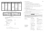
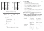
Table 3 gives resistance factors for common flue components for use in the formula. Table 4 contains the
appropriate inlet and outlet flue resistances. (

The flue is likely to be satisfactory if its equivalent

height  exceeds 1m

).

ZZ602/6

4

ZZ602/6

15

c. Main burner lights

i.

Loose electrical connection

Check connections.

but fan fails to run

Fan Delay Control.

after approx. 3 min.

ii.

Fan Delay Control set incorrectly.

Check for correct settings.

iii.

Faulty fan assembly.

Replace, taking care not to damage
impeller.

iv.

Faulty Fan Delay Control.

Replace.

v.

Burner pressure setting incorrect.

Adjust Burner pressure.

d. Main burner operating

i.

Gas rate or burner pressure

Check gas rate and burner pressure

intermittently

setting high.

setting.

with fan running.

ii.

Temperature  rise  excessive.

Adjust fan speed or gas rate accordingly.

iii.

Air filter or return air path

Check filter is clean and air path is clear.

restricted.

iv.

Excessive number of outlets

Open additional outlets.

closed.

v.

Spillage of flue gases.

Carry out spillage test and rectify.

e. Main burner operating

i.

Gas rate or burner pressure

Check gas rate and burner pressure

with intermittent

setting too low.

setting.

fan operation.

ii.

Fan Delay Control set incorrectly.

Check for correct settings.

f. Fan runs for excessive

i.

Fan Delay Control set incorrectly.

Check for correct settings.

period or operates
intermittently after
main burner shuts down.

g. Noisy operation.

i.

Gas pressure too high.

Check burner pressure setting.

ii.

Noisy fan motor.

Replace fan assembly.

iii.

Fan speed setting too high.

Adjust fan speed.

j. Pilot alight but main

i.

Mains electrical supply not

Check mains supply.

burner not igniting.

connected  to  heater.

ii.

Controls not demanding heat

Check that time control and
thermostat are operating correctly.

iii.

6.3A fuse failed.

 Replace. If failure occurs again, check

wiring for short circuits.

iv.

Loose connection to thermostat,

Check connections.

Limit Switch , time control,
Multifunctional Control
or transformer.

v.

Transformer open circuit.

Check with test meter and replace
transformer.

vi.

Multifunctional control faulty.

Replace Multifunctional control.

vii.

Limit Switch faulty.

Short circuit control and replace if
necessary.

viii. Room  thermostat or external

Fit temporary loop in heater thermostat

wiring faulty.

socket. If heater ignites, external circuit
or room thermostat is faulty.

Summary of Contents for JU117

Page 1: ...e 2003 These instructions are to be left with the User or adjacent to the Gas Meter 1 Fig 1 General Layout Diagram 1 1 JU78 JU117 and JU156 are open flued fan assisted Upflow ducted warm air heaters the outputs of which are as follows JU78 23 0kW 82 8MJ h 78 500Btu h JU117 34 3kW 123 4MJ h 117 000Btu h JU156 45 7kW 164 5MJ h 156 000Btu h THESEAPPLIANCESCONFORMTOBS800 1 2 3 4 5 6 7 8 9 10 11 Johnso...

Page 2: ... 3A T6 3A 2 HEATER COMPARTMENTAND CLEARANCES See BS6230 2 1 When a heater is fitted into a compartment the following minimum clearances must be maintained 2 1 1 12mm 0 5in from rear and a side fitted with a blanking plate allowing extra space if a gas supply pipe enters the appliance from this side 2 1 2 600mm 24 in from a side fitted with a louvre side return panel 2 1 3 230mm 9 in from the front...

Page 3: ...e similarly insulated and in addition wrapped with a sound vapour proof barrier and protected from crushing 4 2 2 The duct system should be carefully designed as given in the guidelines in the British System Design Manual to suit the needs of its specific heating requirements and building layout The type of duct system i e radial extended plenum stepped should be installed using the least number o...

Page 4: ... The procedure is based on calculating the equivalent height of the flue under consideration i e that height of the straight vertical circular flue pipe of specific size which will produce the same flow rate as the flue under consideration The equivalent height is calculated from the formula Ki Ko e He Ha x ____________________ Ki Ko a Ke Ha Sum K where He is the height of the equivalent flue Ha i...

Page 5: ...2 x screws securing the Limit Switch and withdraw the control from the appliance 8 12 8 Refitment or replacement is in reverse order 8 13 HEAT EXCHANGERACCESS 8 13 1 Remove the upper and central front doors 8 13 2 Remove the Burner and Controls assembly as detailed in para 8 2 8 13 3 Release the 4 x securing screws and remove heat exchanger access plate and gasket from the front of the draught div...

Page 6: ... reverse order 8 8 CONTROL PANEL REMOVAL 8 8 1 Ensure that the electrical supply to the appliance is isolated 8 8 2 Release the 2 x securing screws and remove the appliance lower front door 8 8 3 At the Control Panel terminal block and referring to Fig 6 disconnect the following a 230V connections L N and E to the Air Circulating Fan at terminals 15 16 and 17 b 230V mains L N and E connections fro...

Page 7: ... except for very small rooms i e bathrooms etc Outlet faces may require partial blanking in order to achieve this 6 3 3 Set the SUMMER AIR CIRCULATION switch to OFF ZZ602 6 7 ZZ602 6 12 8 2 BURNER AND CONTROLS ASSEMBLY REMOVAL 8 2 1 Ensure that the Gas and Electrical supplies are switched OFF 8 2 2 Remove the appliance central front door 8 2 3 Disconnect the Multifunctional Control and Limit Switc...

Page 8: ...switches and summer air circulation switch and that the time control if fitted must be reset following a power failure 7 2 3 How to extinguish the pilot and main burner at the Multifunctional control and switch off electrical supply to the heater 7 2 4 How to remove clean and re fit the air filter if fitted and at what intervals i e fortnightly or weekly for new premises 7 2 5 How to control the h...

Page 9: ...er Pressure Settings ZZ602 6 10 AIRFLOW cfm Table 5 Fan Performance Curve ZZ602 6 9 1 Start button 2 Off button 3 Burner Pressure adjuster 4 Outlet Pressure test point 5 Pilot Adjuster Fig 4 Multifunctional Control 6 6 EXTINGUISHING OF BURNERS AND TEMPERATURE RISE TEST 6 6 1 At the Multifunctional control press the OFF button and ensure that both the Main and Pilot burners extinguish 6 6 2 Remove ...

Page 10: ...er Pressure Settings ZZ602 6 10 AIRFLOW cfm Table 5 Fan Performance Curve ZZ602 6 9 1 Start button 2 Off button 3 Burner Pressure adjuster 4 Outlet Pressure test point 5 Pilot Adjuster Fig 4 Multifunctional Control 6 6 EXTINGUISHING OF BURNERS AND TEMPERATURE RISE TEST 6 6 1 At the Multifunctional control press the OFF button and ensure that both the Main and Pilot burners extinguish 6 6 2 Remove ...

Page 11: ...switches and summer air circulation switch and that the time control if fitted must be reset following a power failure 7 2 3 How to extinguish the pilot and main burner at the Multifunctional control and switch off electrical supply to the heater 7 2 4 How to remove clean and re fit the air filter if fitted and at what intervals i e fortnightly or weekly for new premises 7 2 5 How to control the h...

Page 12: ... except for very small rooms i e bathrooms etc Outlet faces may require partial blanking in order to achieve this 6 3 3 Set the SUMMER AIR CIRCULATION switch to OFF ZZ602 6 7 ZZ602 6 12 8 2 BURNER AND CONTROLS ASSEMBLY REMOVAL 8 2 1 Ensure that the Gas and Electrical supplies are switched OFF 8 2 2 Remove the appliance central front door 8 2 3 Disconnect the Multifunctional Control and Limit Switc...

Page 13: ... reverse order 8 8 CONTROL PANEL REMOVAL 8 8 1 Ensure that the electrical supply to the appliance is isolated 8 8 2 Release the 2 x securing screws and remove the appliance lower front door 8 8 3 At the Control Panel terminal block and referring to Fig 6 disconnect the following a 230V connections L N and E to the Air Circulating Fan at terminals 15 16 and 17 b 230V mains L N and E connections fro...

Page 14: ...2 x screws securing the Limit Switch and withdraw the control from the appliance 8 12 8 Refitment or replacement is in reverse order 8 13 HEAT EXCHANGERACCESS 8 13 1 Remove the upper and central front doors 8 13 2 Remove the Burner and Controls assembly as detailed in para 8 2 8 13 3 Release the 4 x securing screws and remove heat exchanger access plate and gasket from the front of the draught div...

Page 15: ... The procedure is based on calculating the equivalent height of the flue under consideration i e that height of the straight vertical circular flue pipe of specific size which will produce the same flow rate as the flue under consideration The equivalent height is calculated from the formula Ki Ko e He Ha x ____________________ Ki Ko a Ke Ha Sum K where He is the height of the equivalent flue Ha i...

Page 16: ...e similarly insulated and in addition wrapped with a sound vapour proof barrier and protected from crushing 4 2 2 The duct system should be carefully designed as given in the guidelines in the British System Design Manual to suit the needs of its specific heating requirements and building layout The type of duct system i e radial extended plenum stepped should be installed using the least number o...

Page 17: ... 3A T6 3A 2 HEATER COMPARTMENTAND CLEARANCES See BS6230 2 1 When a heater is fitted into a compartment the following minimum clearances must be maintained 2 1 1 12mm 0 5in from rear and a side fitted with a blanking plate allowing extra space if a gas supply pipe enters the appliance from this side 2 1 2 600mm 24 in from a side fitted with a louvre side return panel 2 1 3 230mm 9 in from the front...

Page 18: ...e 1 1 1 9 397819 BOS02394 Electrode lead 1 1 1 10 U780 0700000 Burner and Controls Assembly 1 U117 0700000 Burner and Controls Assembly 1 U560 0700000 Burner and Controls Assembly 1 11 U780 0752000 Main Burner 2 3 4 12 1000 0703720 Main Injector BRAYCat 33 1250 2 3 4 13 BOS01676 4 Cross Lighting Injector InterAlbion T100 1 1 14 S00461 Heat Exchanger exchange kit 1 S00462 Heat Exchanger exchange ki...

Page 19: ...e 2003 These instructions are to be left with the User or adjacent to the Gas Meter 1 Fig 1 General Layout Diagram 1 1 JU78 JU117 and JU156 are open flued fan assisted Upflow ducted warm air heaters the outputs of which are as follows JU78 23 0kW 82 8MJ h 78 500Btu h JU117 34 3kW 123 4MJ h 117 000Btu h JU156 45 7kW 164 5MJ h 156 000Btu h THESEAPPLIANCESCONFORMTOBS800 1 2 3 4 5 6 7 8 9 10 11 Johnso...

Reviews: