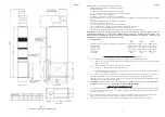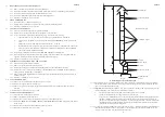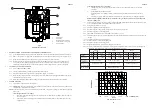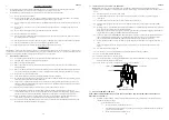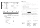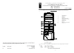
Fig. 2
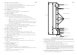
Worked example of equivalent flue height
5.1.12 Where flue blocks are used, builders should ensure that no obstruction is created during erection. The installer
should ensure that the connection flue does not project beyond the internal wall of the flue blocks and that there
is provision for examination and servicing.
5.1.13
Important:
Before installing the appliance, carry out a visual check of the flue system as directed in the relevant
section of BS5440 Pt.1, then check the flue performance as follows:-
a.
Close all doors and windows in the room in which the appliance is to be installed.
b.
Introduce some heat into the flue, using a blow torch or other means.
c.
Carry out a flow visualisation check with a smoke pellet at the intended position for the appliance. Ensure
that there is discharge of smoke from the correct terminal only, and no spillage into the room. Smoke
coming out of other than the correct terminal only, or a down draught or ‘no flow’ condition, indicates that
the flue has failed the test, and the appliance shall not be connected until the defect has been found and
rectified, and the test satisfactorily completed.
5.1.14 An approved terminal should always be used; a ridge terminal or ‘GC1’ terminal is specifically recommended. The
latter should be positioned in a free air space where it is not shielded by any structure. A minimum of 1m (3ft)
from any vertical or inclined roof structure must be allowed for.
1.6m
4.6m
H
a
= 6.2m
STET Terminal
2 x 300 mm lengths
4 x 1000 mm lengths
45
O
bend
45
O
bend
2 x 300 mm lengths
300 mm length
Appliance draught
diverter
100 mm dia flue pipe
6
ZZ602/6
13
ZZ602/6
8.6
MULTIFUNCTIONAL CONTROL REMOVAL:
8.6.1
Remove the Burner and Controls Assembly as detailed in 8.2
8.6.2
Disconnect the Thermocouple and adapter at the Multifunctional Control, avoiding damage to the capillary.
8.6.3
Disconnect the Pilot Feed Pipe from the Multifunctional Control.
8.6.4
Disconnect the Multifunctional Control input and output supply feeds.
8.6.5
Refitting or replacement is in reverse order.
8.7
PIEZO UNIT REMOVAL:
8.7.1
Disconnect the 2 x conductors from Piezo unit.
8.7.2
Release the Piezo retaining nut and remove the Piezo unit from its mounting bracket.
8.7.3
Refitting or replacement is in reverse order.
8.8
CONTROL PANEL REMOVAL:
8.8.1
Ensure that the electrical supply to the appliance is isolated.
8.8.2
Release the 2 x securing screws and remove the appliance lower front door.
8.8.3
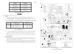
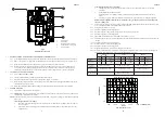
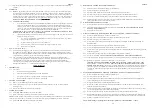
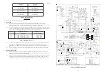
At the Control Panel terminal block, (and referring to Fig. 6), disconnect the following:
a.
230V connections ‘
L
’, ‘
N
’ and ‘
E
’ to the Air Circulating Fan at terminals ‘
15
’, ‘
16
’ and ‘
17
’.
b.
230V mains ‘
L
’, ‘
N
’ and ‘
E
’ connections from terminals marked
230V 50 Hz
‘
L
’ and ‘
N
’, and the earth
stud.
c.
Thermostat connections from connection block terminals ‘
8
’, ‘
9
’ and ‘
11
’.
d.
Multifunctional Control connections from connection block terminals ‘
5
’ (YELLOW) and ‘
7
’ (BLACK).
e.
Fan Delay Control connections from connection block terminals ‘
1
’ (BROWN), ‘
2
’ (BLUE with RED
sleeve) and earth stud (GREEN/YELLOW).
8.8.4
Disconnect the 2 BROWN conductors from the SUMMER AIR CIRCULATION switch.
8.8.5
Whilst supporting the Control Panel, release the 4 securing screws and withdraw the Control Panel from the
appliance, releasing the wiring from cable clamps and grommets as required.
8.8.6
Refitting or replacement is in reverse order.
8.9
AIR CIRCULATING FAN, REMOVAL AND CLEANING:
8.9.1
Ensure that the electrical supply is isolated.
8.9.2
Remove the Control Panel as detailed in para 8.8
8.9.3
Release the securing screw from the upper front flange of the fan skirt, and withdraw the flange.
8.9.4
Release the 2 screws securing the Fan Assembly to the fan chamber floor, and withdraw the Fan Assembly by
sliding it forward, avoiding damage to fan blades.
8.9.5
Remove all dust from impeller and motor, avoiding damage to the fan blades and taking care not to disturb the
balance of the fan..
8.9.6
Refitting or replacement is in reverse order.
8.10
CAPACITOR REMOVAL:
8.10.1 Remove the Air Circulating Fan as detailed in para 8.9.1 to 8.9.4
8.10.2 Release the capacitor from the retaining clip.
8.10.3 Remove the protective cover from the capacitor and disconnect the 2 black conductors from the capacitor
terminals.
8.10.4 Refitment or replacement is in reverse order.
8.11
FAN DELAY CONTROL REMOVAL:
8.11.1 Ensure that the electrical supply is isolated.
8.11.2 Remove the appliance central front door.
8.11.3 Release the 2 x screws securing the Fan Delay Control cover, and withdraw the cover.
8.11.4 Disconnect ‘
LOAD
’ (BLUE), ‘
COMM
’ (BROWN) and
EARTH
(GREEN/YELLOW) connections from the Fan
Delay Control.
8.11.5 Release the 2 securing screws and withdraw the Fan Delay Control.
8.11.6 Refitment or replacement is in reverse order.


