background image

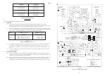
ZZ602/6

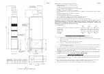
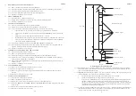
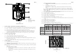
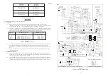
Fig. 6

JU Series Air Heaters Principle Dimensions

17

2

ZZ602/6

6Installation shall be in accordance with the current editions of:-

Building Standards (Scotland) (Consolidation) Regulations.
Building Regulations.
Gas Safety (Installation and Use) Regulations (as amended).
BS 7671 Institute of Electrical Engineers (I.E.E.) Wiring Regulations.
BS 5440 Pt. 1 (Flues for Gas Appliances).
BS 5440 Pt. 2 (Installation of ventilation for gas appliances)
BS6230 Installation of Gas Fired Forced convection Air Heaters for Commercial and Industrial space heating (2nd family
gases).
British System Design Manual “Gas Fired Warm Air Heating”.
Model and Local Authority Bye-laws.
IM/2

Purging procedures for non-domestic gas installations.

IM/5

Soundness testing procedures for industrial and commercial gas installations.

IM/11 Flues for commercial and industrial gas fired boilers and air heaters.
IM/16 Notes on installation of pipework (excluding domestic installations of 25mm and below).

IMPORTANT: STATUTE LAW DEFINES THAT ALL GAS APPLIANCES MUST BE INSTALLED BY
COMPETENT PERSONS, (i.e. CORGI REGISTERED INSTALLERS) IN ACCORDANCE WITH THE GAS
SAFETY (INSTALLATION AND USE) REGULATIONS (CURRENT EDITION). FAILURE TO COMPLY WITH
THESE REGULATIONS MAY LEAD TO PROSECUTION.

1.2

GENERAL DATA

JU78

JU117

JU156

Appliance height (excluding air discharge top or swivel heads)

1830mm (72in) 1830mm (72in) 1830mm (72in)

Appliance width

375mm (14.8in) 525mm (20.7in) 675mm (26.2in)

Appliance depth

778mm (30.6in) 778mm (30.6in) 778mm (30.6in)

Appliance weight

110kg (242lb)

140kg (308lb)

220kg (484lb)

Flue diameter

125mm (5in)

150mm (6in)

150mm (6in)

Fuse rating

T6.3A

T6.3A

T6.3A

2.

HEATER COMPARTMENT AND CLEARANCES 

(See BS6230)

2.1

When a heater is fitted into a compartment, the following minimum clearances must be maintained:

2.1.1

12mm (0.5in ) from rear, and a side fitted with a blanking plate, allowing extra space if a gas supply pipe enters the
appliance from this side.

2.1.2

600mm (24 in) from a side fitted with a louvre side return panel.

2.1.3

230mm ( 9 in ) from the front for combustion air supply.

2.1.4

Consideration should also be given to the space required for the removal and replacement of the filter tray and the
entry of the gas and electrical supplies.

2.2

For service access, a minimum of 750mm (30ins) is required at the front of the heater. Space must also be allowed, in a
compartment installation, to permit the removal of the heater. Where clearances between the appliance and the
compartment are less than 75mm, the internal surface of the compartment must be lined with non-combustible material.
The compartment must be of a fixed rigid structure.

2.3

IMPORTANT:

 When the heater is installed in a compartment, the ‘

SAFETY

’ label supplied with the heater 

MUST BE

AFFIXED 

in a prominent position on the 

INSIDE 

of the 

COMPARTMENT DOOR

.

3.

VENTILATION AND COMBUSTION AIR

3.1

When the air heater is free standing or ducted, but in an open area, there must be a adequate supply of air for combustion
in accordance with BS 6230 Clause 12.1.1.  The openings should be sited so that they cannot be easily blocked (refer to
BS 6230 Clause 12.1.3).

3.2

Where natural ventilation is used for compartment or plant rooms, suitable permanent openings at low and high level,
communicating directly with outside air, shall be provided in accordance with BS 6230 Clause 12.1.5.

3.3

If the installation includes more than one heater, the ventilation requirements of BS 6230 must be observed.

Summary of Contents for JU117

Page 1: ...e 2003 These instructions are to be left with the User or adjacent to the Gas Meter 1 Fig 1 General Layout Diagram 1 1 JU78 JU117 and JU156 are open flued fan assisted Upflow ducted warm air heaters the outputs of which are as follows JU78 23 0kW 82 8MJ h 78 500Btu h JU117 34 3kW 123 4MJ h 117 000Btu h JU156 45 7kW 164 5MJ h 156 000Btu h THESEAPPLIANCESCONFORMTOBS800 1 2 3 4 5 6 7 8 9 10 11 Johnso...

Page 2: ... 3A T6 3A 2 HEATER COMPARTMENTAND CLEARANCES See BS6230 2 1 When a heater is fitted into a compartment the following minimum clearances must be maintained 2 1 1 12mm 0 5in from rear and a side fitted with a blanking plate allowing extra space if a gas supply pipe enters the appliance from this side 2 1 2 600mm 24 in from a side fitted with a louvre side return panel 2 1 3 230mm 9 in from the front...

Page 3: ...e similarly insulated and in addition wrapped with a sound vapour proof barrier and protected from crushing 4 2 2 The duct system should be carefully designed as given in the guidelines in the British System Design Manual to suit the needs of its specific heating requirements and building layout The type of duct system i e radial extended plenum stepped should be installed using the least number o...

Page 4: ... The procedure is based on calculating the equivalent height of the flue under consideration i e that height of the straight vertical circular flue pipe of specific size which will produce the same flow rate as the flue under consideration The equivalent height is calculated from the formula Ki Ko e He Ha x ____________________ Ki Ko a Ke Ha Sum K where He is the height of the equivalent flue Ha i...

Page 5: ...2 x screws securing the Limit Switch and withdraw the control from the appliance 8 12 8 Refitment or replacement is in reverse order 8 13 HEAT EXCHANGERACCESS 8 13 1 Remove the upper and central front doors 8 13 2 Remove the Burner and Controls assembly as detailed in para 8 2 8 13 3 Release the 4 x securing screws and remove heat exchanger access plate and gasket from the front of the draught div...

Page 6: ... reverse order 8 8 CONTROL PANEL REMOVAL 8 8 1 Ensure that the electrical supply to the appliance is isolated 8 8 2 Release the 2 x securing screws and remove the appliance lower front door 8 8 3 At the Control Panel terminal block and referring to Fig 6 disconnect the following a 230V connections L N and E to the Air Circulating Fan at terminals 15 16 and 17 b 230V mains L N and E connections fro...

Page 7: ... except for very small rooms i e bathrooms etc Outlet faces may require partial blanking in order to achieve this 6 3 3 Set the SUMMER AIR CIRCULATION switch to OFF ZZ602 6 7 ZZ602 6 12 8 2 BURNER AND CONTROLS ASSEMBLY REMOVAL 8 2 1 Ensure that the Gas and Electrical supplies are switched OFF 8 2 2 Remove the appliance central front door 8 2 3 Disconnect the Multifunctional Control and Limit Switc...

Page 8: ...switches and summer air circulation switch and that the time control if fitted must be reset following a power failure 7 2 3 How to extinguish the pilot and main burner at the Multifunctional control and switch off electrical supply to the heater 7 2 4 How to remove clean and re fit the air filter if fitted and at what intervals i e fortnightly or weekly for new premises 7 2 5 How to control the h...

Page 9: ...er Pressure Settings ZZ602 6 10 AIRFLOW cfm Table 5 Fan Performance Curve ZZ602 6 9 1 Start button 2 Off button 3 Burner Pressure adjuster 4 Outlet Pressure test point 5 Pilot Adjuster Fig 4 Multifunctional Control 6 6 EXTINGUISHING OF BURNERS AND TEMPERATURE RISE TEST 6 6 1 At the Multifunctional control press the OFF button and ensure that both the Main and Pilot burners extinguish 6 6 2 Remove ...

Page 10: ...er Pressure Settings ZZ602 6 10 AIRFLOW cfm Table 5 Fan Performance Curve ZZ602 6 9 1 Start button 2 Off button 3 Burner Pressure adjuster 4 Outlet Pressure test point 5 Pilot Adjuster Fig 4 Multifunctional Control 6 6 EXTINGUISHING OF BURNERS AND TEMPERATURE RISE TEST 6 6 1 At the Multifunctional control press the OFF button and ensure that both the Main and Pilot burners extinguish 6 6 2 Remove ...

Page 11: ...switches and summer air circulation switch and that the time control if fitted must be reset following a power failure 7 2 3 How to extinguish the pilot and main burner at the Multifunctional control and switch off electrical supply to the heater 7 2 4 How to remove clean and re fit the air filter if fitted and at what intervals i e fortnightly or weekly for new premises 7 2 5 How to control the h...

Page 12: ... except for very small rooms i e bathrooms etc Outlet faces may require partial blanking in order to achieve this 6 3 3 Set the SUMMER AIR CIRCULATION switch to OFF ZZ602 6 7 ZZ602 6 12 8 2 BURNER AND CONTROLS ASSEMBLY REMOVAL 8 2 1 Ensure that the Gas and Electrical supplies are switched OFF 8 2 2 Remove the appliance central front door 8 2 3 Disconnect the Multifunctional Control and Limit Switc...

Page 13: ... reverse order 8 8 CONTROL PANEL REMOVAL 8 8 1 Ensure that the electrical supply to the appliance is isolated 8 8 2 Release the 2 x securing screws and remove the appliance lower front door 8 8 3 At the Control Panel terminal block and referring to Fig 6 disconnect the following a 230V connections L N and E to the Air Circulating Fan at terminals 15 16 and 17 b 230V mains L N and E connections fro...

Page 14: ...2 x screws securing the Limit Switch and withdraw the control from the appliance 8 12 8 Refitment or replacement is in reverse order 8 13 HEAT EXCHANGERACCESS 8 13 1 Remove the upper and central front doors 8 13 2 Remove the Burner and Controls assembly as detailed in para 8 2 8 13 3 Release the 4 x securing screws and remove heat exchanger access plate and gasket from the front of the draught div...

Page 15: ... The procedure is based on calculating the equivalent height of the flue under consideration i e that height of the straight vertical circular flue pipe of specific size which will produce the same flow rate as the flue under consideration The equivalent height is calculated from the formula Ki Ko e He Ha x ____________________ Ki Ko a Ke Ha Sum K where He is the height of the equivalent flue Ha i...

Page 16: ...e similarly insulated and in addition wrapped with a sound vapour proof barrier and protected from crushing 4 2 2 The duct system should be carefully designed as given in the guidelines in the British System Design Manual to suit the needs of its specific heating requirements and building layout The type of duct system i e radial extended plenum stepped should be installed using the least number o...

Page 17: ... 3A T6 3A 2 HEATER COMPARTMENTAND CLEARANCES See BS6230 2 1 When a heater is fitted into a compartment the following minimum clearances must be maintained 2 1 1 12mm 0 5in from rear and a side fitted with a blanking plate allowing extra space if a gas supply pipe enters the appliance from this side 2 1 2 600mm 24 in from a side fitted with a louvre side return panel 2 1 3 230mm 9 in from the front...

Page 18: ...e 1 1 1 9 397819 BOS02394 Electrode lead 1 1 1 10 U780 0700000 Burner and Controls Assembly 1 U117 0700000 Burner and Controls Assembly 1 U560 0700000 Burner and Controls Assembly 1 11 U780 0752000 Main Burner 2 3 4 12 1000 0703720 Main Injector BRAYCat 33 1250 2 3 4 13 BOS01676 4 Cross Lighting Injector InterAlbion T100 1 1 14 S00461 Heat Exchanger exchange kit 1 S00462 Heat Exchanger exchange ki...

Page 19: ...e 2003 These instructions are to be left with the User or adjacent to the Gas Meter 1 Fig 1 General Layout Diagram 1 1 JU78 JU117 and JU156 are open flued fan assisted Upflow ducted warm air heaters the outputs of which are as follows JU78 23 0kW 82 8MJ h 78 500Btu h JU117 34 3kW 123 4MJ h 117 000Btu h JU156 45 7kW 164 5MJ h 156 000Btu h THESEAPPLIANCESCONFORMTOBS800 1 2 3 4 5 6 7 8 9 10 11 Johnso...

Reviews: