8
| SOLARIS SYNTHESIZER
Likewise for the Filter Mixer section – the
fi
rst four
knobs are mixer inputs, and you can select from the
Source popup lists below each knob to determine the
signal input for each of these.
Signal Flow
The sound sources are connected to the four inputs of
each
fi
lter mixer. Since there are many available sound
sources, but only four inputs to each
fi
lter section, a
popup selector list is used to assign a sound source to
a
fi
lter mixer input.
No sound will be produced at the output of a fi lter mixer if it is
disabled or if the fi lter Mute button—located in the lower left
corner of the synth window—for that fi lter channel is in the
off position.
The sound sources are routed through the selected
fi
lter(s) (if enabled), then through the Pan circuit. There
are several controls over the
fi
nal audio level of the
Solaris: the Master Volume, the Poly Level, and the
Overdrive. Of these, the Poly Level is NOT stored in
the presets. The idea here is that you set the number of
voices you expect to be using for most of the time, then
you adjust the Poly Level so that there is minimum clip-
ping. This handles the overall headroom of the synth’s
output, so you’ll always want to check this level if you
hear some clipping, but can’t determine why in the
normal signal path analysis.
The Master Volume is at the end of the signal path, al-
lowing you to have high settings for the Overdrive, with-
out destroying your speakers or your ears! However,
please be careful to not hold down notes while chang-
ing presets, especially if you are selecting a preset with
high Overdrive settings, as you may hear some loud
sounds during the transition.
Remember that each preset may be changing the DSP
load through enabling/disabling sections, and if so will
take a bit longer than the average preset change.
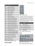
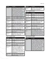
The main sound sources available within Solaris are:
Sound Source
Page Tab Label
Multimode Oscillators
MM
Wavetable Oscillators
WT
RDX Module Slots
RDX 1/2
WAV Oscillators
WAV
CEM Oscillators
CEM
Modular Windows
Mod
FM Oscillators
FM
AM (cross modulation) proces-
sors
AM / x Mult
Sound Source
Page Tab Label
Rotor processors
Rotor
Vector Synthesis Mixers
VS
Left, Right, 3, and 4 External
Inputs
[These appear in fi lter mixers,
Rotors, AM, Vector and LFO
Mix/Blend source lists only]
RD Mod Slots
Listed in the Global RD Mod
section
LFOs
[These appear in Rotors, AM,
Vector and LFO Mix/Blend
source lists only]
Filter Outputs
[These appear in fi lter mixers,
Rotors, AM, Vector]
Sound Sources
Table 1:
Each input appears separately in the Mixer Source
lists. Here’s what a typical Source popup list will look
like:
OFF
SMO
LFO-a
LFO-b
LFO-c
LFO Mix
Env Foll
Shaper
LoopEG
Env 1
Env 2
Env 3
Env 4
AmpEG
Vel
AT
Mod Wh
AT+MW
KeyTrk
Seq A
Seq B
Seq C
CC 1
CC 2
CC 3
CC 4
MMOsc1
MMOsc2
EnOsc
WT1
WT2
RDX 1
RDX 2
Wav 1
Wav 2
CEM 1
CEM2
Mod 1
Mod 2
FM 1
FM 2
AM 1
AM 2
Rotor 1
Rotor 2
VS 1
VS 2
Filter 1
Filter 2
Filter 3
Filter 4
Mixer 1
Mixer 2
Mixer 3
Mixer 4
VCA 1
VCA 2
VCA 3
VCA 4
Ext L
Ext R
Ext 3
Ext 4
WhNoiz
PinkNoiz
FiltNoiz
xMult1
xMult2
xMult3
xMult4
KeyLv1
KeyLv2
KeyLv3
KeyLv4
ModCh1
ModCh2
ModCh3
Typical source popup list
Table 2:
An important point is that the Rotor, AM, and Vector
processors do not output sound by themselves; rather,
they require selecting from among the other sound
sources to produce their unique output. However, for
practical uses, these still act as ‘sound sources’.
The 8 Global RD Module Slots from Solaris v4.0 have
been removed, and replaced by additional ‘taps’ of
the audio path signal at various stages. You can now
choose the source for modulation directly from the Mix-
er, post-
fi
lter, or post-VCA, making the entire contoured
signal path available for feedback loops.


