FILTERS |
23
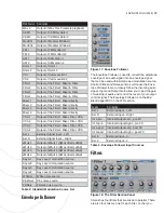
Filter Type
Description
RD
Accepts any RD series II
fi
lter mod-
ule, so that you can customize the
fi
lter used here
Modular
A Modular Window is available for
the
fi
lter con
fi
guration; clicking on
the small, gray button to the left of
the
fi
lter popup list will open the
Window
Red Dwarf Slot and
Table 11:
Modular Window
Filter Routing
Table 12: Filter 2 Input Options
The Input parameter allows you to route any of the 4
Filter Mixers to the input of any
fi
lter. In addition, each
fi
lter can take the output of any other
fi
lter as its input.
For example, if you have Filter 2 as a high pass
fi
lter
with some post-
fi
lter distortion, you can process that
with Filter 1’s FX, pre- or post-
fi
lter as well.
Solaris’s 4
fi
lters are hardwired in parallel, and each
has it’s own VCA and panning circuit. The Input param-
eter can be used to wire
fi
lters in series, but it is impor-
tant to remember that the output of all 4 parallel
fi
lters
will be heard in the overall mix unless you mute all but
the
fi
nal
fi
lter in the series. Muting a
fi
lter will take it
out fo the parallel path entirely. If you desire some of
a
fi
lter’s output to appear in the mix, you can reduce
the ENV amount of the AmpEG on the Outputs page to
drop the
fi
lter’s overall output in the signal path.
Filter Mixer
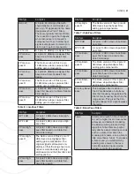
Figure 20: The Filter Mixer Panel
The Filter Mixer consists of 4 pages of controls, control-
ling Mix Level, Mix Modulation, Mix Effects and Output.
These sections can be accessed by clicking on the
page buttons at the top of the Filter Mixer section.
Mix Level Page
Control
Description
Blue LED
switch
On/Off to unload Mixer from the
DSP
Mix Mod
Enable LED
switch
Enable/Disable to load/unload Mix
Mod section from the DSP
4 inputs
Each with a bipolar mix level, to
provide inverted phase. Inverting
the phase with 2 or more oscillators
on can cause subtle but notable
changes in the harmonic content
Level
The
fi
nal level of the Filter Mixer
can be controlled by an extensive
list of mod sources.
Init Pan
This is the Initial Pan setting
Pan On/Off
With Pan OFF, the overall signal
output is increased
Pan Mod
This provides a modulation path for
the pan position
Mix Level Controls
Table 13:
Mixer Modulation
(Mix Mod)
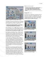
Figure 21: Mixer Modulation Controls
Mix Mod allows you to modulate each of the 16 mixer
input levels individually from the full mod source list.
The Mix Levels and Mod Amounts are independent
parameters, so you can have an amount of modulation
and an offset mix level.
Use the page buttons to switch the Mixer display for
Levels to Mix Modulation.
For effective modulation of the mixer inputs, you need
the initial mixer level to be at zero. Then, select a mod
source (such as Env 1 or an LFO), and increase the
mod amount with the knob above the mod list selec-
tor. The Amounts are bipolar, which won’t always make
sense, but does allow for inverted phase of the mod
source. If you want to add some offset to the signal,
just raise the initial mixer level for the input.
Also, because the added circuitry of the Mix Mod sec-
tion takes up a fair amount of DSP , there is an Enable/
Disable button in the upper left corner of each section,
below the Mixer Enable button, and is colored red


