PAGE 1 CONTROLS |
39
values are copied from the buffer into the new pattern
location.
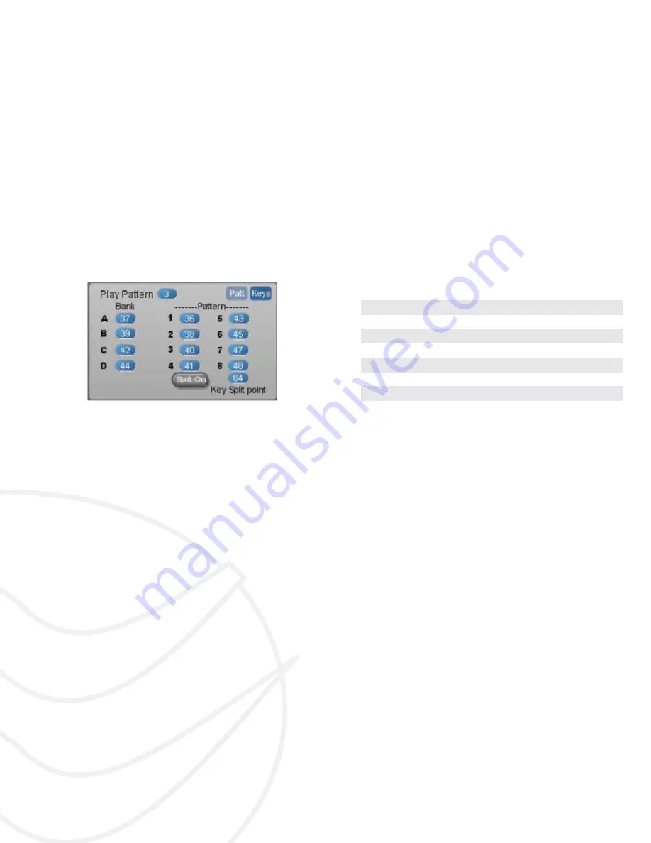
Split On – you can use your MIDI keyboard (or incom-
ing MIDI notes) to remotely control the selection of
banks and patterns (see the Pattern Keys tab explana-
tion below). To do this, you may want to isolate a lower
portion of your keyboard to prevent unwanted notes to
sound. When you turn on the Split On button, the Key
Split point determines the note value below which the
Keys assignments are activated. No synthesizer voices
are played at or below this split point.
Pattern Keys
Figure 53: Pattern Keys Panel
When the Split On button is on, the note values dis-
played here will be used to automatically select the
associated Bank or Pattern. Setting Bank B to 60, for
example, will select Bank B when middle C is pressed
on the keyboard. These only function when Key Split is
ON.
Page 1 Controls
Refer to the fi gures at the beginning of the Step Sequencer Sec-
tion.
For each Sequence Row (A, B, or C) there are 4 pa-
rameters. The topmost row is labeled ‘ Gate’. Using the
check boxes, you determine if the step will send out a
Gate signal at that point. This gate signal’s duration is
half the time of the MIDI clock. The Hold button causes
the gate output to last for the full length of the clock, so,
in essence it causes the gate to stay on until the next
step that does not have a Hold button enabled. (That
step is used to turn off the note, so the next gate on
event will be the following step.)
The Glide function offers 3 positions - off (dark blue),
linear (green), and exponential (orange). It is actually
a function of an internal pitch envelope that causes the
glide effect, not true pitch glide from one step to the
next. There’s also a knob setting the range for each
row, but the actual calculation of this pitch envelope is
somewhat obscure (no explanation of it is in the Scope
documentation), so I suggest playing around with these
settings until you get the desired effect.
The fourth row produces the actual control values for
each sequence row. There is a difference between row
A and the B-C rows; Row A will /- 24 semi-
tones, whereas B and C /- 127 semitones. This
wider range for B and C is necessary to control
fi
lter
cutoffs or shape and pulse width parameters, since
they need the full control range of the system. Using
the knobs to set oscillator pitches with row B and C is
a lot harder this way, so typing in the values directly is
usually the most ef
fi
cient way to enter precise se-
quence values.
To adjust the Steps or Swing values, simply click in the
display window, and select new values from the popup
list.
There are independent Reset buttons for each section of both
sequencer pages. This resets all parameters to their default
position.
New: an exponential Lag control has been add-
ed for each sequence row output, producing an
overall slewing or ‘gliding’ of the control signal.
Page 2 Controls
Refer to the fi gures at the beginning of the Step Sequencer Sec-
tion.
For each Sequence Row (A, B, or C) there are 2 sets
of knobs. The upper row is labeled Env Level, and
controls the velocity input of the overall envelope level
(hence the values of 0-127), using the envelope as-
signed in the Gate Assign section.
The second row is labeled ‘Env Time’, and these val-
ues will affect all assigned envelope segments’ times
simultaneously, with a bipolar amount (giving shorter
or longer times). These settings interact with the initial
envelope settings, and you may
fi
nd that you will need
to adjust the initial envelope times to be the maximum
you wish, with these values acting upon those initial
settings.
Envelope Level
(Env Level)
These values get substituted for the normal velocity
control of the envelope level. At 0 value there should be
no output; at 127, full output.
Envelope Time
(Env Time)
These values get added or subtracted to the enve-
lope’s segments (all segments, equally). The effect is
not always noticeable, depending on the settings. The
initial settings have to have enough leeway in them to


