SECTION 5 - CONTROL COMPONENTS
3121222
– JLG Lift –
5-19
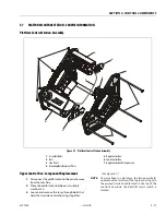
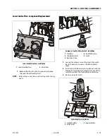
Lower Control Box - Component Replacement
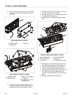
1.
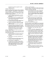
Remove the four (4) attach screws and remove
the cover from the other half.
NOTE:
Note wiring connections and routing when taking
apart.
1.
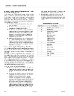
Loosen the release screw, then spin the switch
base if necessary to access the barrel release
lever.
2.
Pull the barrel release lever straight out with the
blade of a screwdriver and pull barrel out of the
switch base from the front of the control box.
3.
Reverse steps to install.
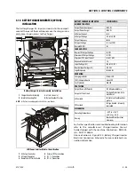
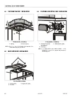
Lower Control Box Cover - Installation
1.
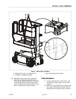
Lower Control Box Cover
2.
Attach Screws
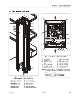
Emergency Stop/Shut-Down Switch - Installation
1.
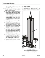
Switch Base
2.
Switch Button/Barrel
3.
Base Release Screw
4.
Barrel Release Lever
5.
Switch
Joystick Control - Installation
1.
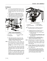
Joystick Assembly
2.
Attach Screws
3.
Lower Control Box
Summary of Contents for 1230ES
Page 1: ...AS NZS Service and Maintenance Manual Model s 1230ES P N 3121222 June 22 2017 ...
Page 2: ...NOTES ...
Page 24: ...SECTION 1 MACHINE SPECIFICATIONS 1 12 JLG Lift 3121222 NOTES ...
Page 32: ...SECTION 2 GENERAL SERVICE INFORMATION 2 8 JLG Lift 3121222 NOTES ...
Page 78: ...SECTION 4 BASE COMPONENTS 4 40 JLG Lift 3121222 NOTES ...
Page 104: ...SECTION 5 CONTROL COMPONENTS 5 26 JLG Lift 3121222 NOTES ...
Page 158: ...SECTION 8 DIAGNOSTIC TROUBLE CODES 8 22 JLG Lift 3121222 NOTES ...
Page 198: ...SECTION 9 GENERAL ELECTRICAL INFORMATION SCHEMATICS 9 40 JLG Lift 3121222 ...
Page 199: ...SECTION 9 GENERAL ELECTRICAL INFORMATION SCHEMATICS 3121222 JLG Lift 9 41 ...
Page 200: ...SECTION 9 GENERAL ELECTRICAL INFORMATION SCHEMATICS 9 42 JLG Lift 3121222 ...
Page 202: ...SECTION 9 GENERAL ELECTRICAL INFORMATION SCHEMATICS 9 44 JLG Lift 3121222 NOTES ...


