background image

SECTION 6 - MAST COMPONENTS

3121222

– JLG Lift –

6-17

Hydraulic Cylinder Component Inspection

Cylinder Rod

There should be no scratches or pits deep enough to catch
the fingernail. Pits that go to the base metal are unaccept-
able. Scratches that catch the fingernail but are not to the
base metal, less than 0.5 inch long and primarily in the cir-
cumferential direction are acceptable provided they can-
not cut the rod seal. Chrome should be present over the
entire surface of the rod and the lack thereof is unaccept-
able. In the event that an unacceptable condition occurs,
the rod should be repaired or replaced.

Cylinder Head (Gland)

Visually inspect the inside bore for scratches or polishing.
Deep scratches are unacceptable. Polishing indicates
uneven loading and when this occurs, the bore should be
checked for out-of-roundness. If out-of-roundness exceed
0.007", this is unacceptable. Check the condition of the
dynamic seals (wiper, rod seals) looking particularly for
metallic particles embedded in the seal surface. It is nor-
mal to cut the static seal on the retaining ring groove
upon disassembly. Remove the rod seal, static o-ring and
backup and rod wiper. Damage to the seal grooves, partic-
ularly on the sealing surfaces, is unacceptable. In the event
that an unacceptable condition occurs, the head should
be replaced.

Piston

Visually inspect the outside surface for scratches or polish-
ing. Deep scratches are unacceptable. Polishing indicates
uneven loading and when this occurs, the diameter
should be checked for out-of-roundness. If out-of-round-
ness exceeds 0.007", this is unacceptable. Check the condi-
tion of the dynamic seals and bearings looking
particularly for metallic particles embedded in the bearing
and in the piston seal surface. Remove the seals and bear-
ings. Damage to the seal grooves, particularly on the seal-
ing surfaces, is unacceptable. In the event that an
unacceptable condition occurs, the piston should be
replaced.

Tube Assembly

Visually inspect the inside bore for scratches and pits.
There should be no scratches or pits deep enough to catch
the fingernail. Scratches that catch the fingernail but are
less than 0.5 inch long and primarily in the circumferential
direction are acceptable provided they cannot cut the pis-
ton seal. The roughness of the bore should be between 10
and 20 μ inches RMS. Significant variation (greater than 8
μ inches difference) are unacceptable. In the event that an
unacceptable condition occurs, the tube assembly should
be repaired or replaced.  

Hydraulic Cylinder - Assembly

NOTE:

Prior to cylinder assembly, ensure the proper JLG
seal kits are used, see the JLG Parts Manual.

APPLY A LIGHT FILM OF THE HYDRAULIC OIL TO BE USED FOR OPERA-
TION TO ALL COMPONENTS TO BE ASSEMBLED, EXCEPT THE THREADED
AREAS WHERE LOCTITE IS TO BE APPLIED.

Cylinder Assembly

This procedure is same for all three cylinders.

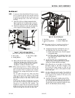
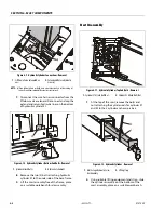
1.

Reassemble the piston/compression spring/pis-
ton guide onto the end of the cylinder rod 
secure using the piston retaining ring

(See Figure 

6-20.)

EXTREME CARE SHOULD BE TAKEN WHEN INSTALLING THE CYLINDER
ROD, HEAD, AND PISTON INTO THE CYLINDER BARREL. AVOID PULL-
ING THE ROD OFF CENTER, WHICH COULD CAUSE DAMAGE TO THE PIS-
TON AND CYLINDER BARREL SURFACES.

2.

Lubricate the piston assembly and rod with 
hydraulic oil, slide the rod assembly into the cyl-
inder barrel.

3.

Install new o-rings and seals into the cylinder 
head gland.

4.

Lubricate the o-rings and seals with hydraulic oil 
then carefully slide the gland assembly onto the 
end of the cylinder rod and into the end of the 
cylinder barrel.

5.

Rotate the gland until the hole for the retaining 
ring is lined up with the hole in the cylinder bar-
rel.

6.

Insert a new retaining ring into the slot with the 
hook end of the retaining ring facing down and 
inserted into the hole in the gland. 

(See Figure 6-

19.)

7.

Using the proper spanner wrench (48mm - 
1.889" diameter) slowly rotate the gland 360° 
until all the retaining ring has pulled into the 
slot. Fill the open slot with a silicone sealant to 
prevent dirt from entering. 

Summary of Contents for 1230ES

Page 1: ...AS NZS Service and Maintenance Manual Model s 1230ES P N 3121222 June 22 2017 ...

Page 2: ...NOTES ...

Page 3: ...TOR HYDRAULIC SYSTEM SAFETY It should be noted that the machines hydraulic systems operate at extremely high potentially dangerous pres sures Every effort should be made to relieve any system pressure prior to disconnecting or removing any por tion of the system MAINTENANCE FAILURE TO COMPLY WITH SAFETY PRECAUTIONS LISTED IN THIS SEC TION COULD RESULT IN MACHINE DAMAGE PERSONNEL INJURY OR DEATH AN...

Page 4: ...7 Manual Revised March 22 2007 Manual Revised March 30 2007 Manual Revised April 11 2007 Manual Revised May 15 2007 Manual Revised November 30 2007 Manual Revised June 4 2008 Manual Revised November 11 2008 Manual Revised August 18 2010 Manual Revised August 31 2011 Manual Revised February 22 2012 Manual Revised April 22 2013 Manual Revised February 8 2017 Manual Revised June 22 2017 ...

Page 5: ... MACHINE PREPARATION INSPECTION AND MAINTENANCE 2 1 General 2 1 Preparation Inspection and Maintenance 2 1 Pre Start Inspection 2 1 Pre Delivery Inspection and Frequent Inspection 2 1 Annual Machine Inspection 2 1 Preventative Maintenance 2 1 2 2 PREVENTIVE MAINTENANCE AND INSPECTION SCHEDULE 2 2 Maintenance and Inspection Table Codes 2 4 Footnotes 2 4 2 3 SERVICING AND MAINTENANCE GUIDELINES 2 5 ...

Page 6: ... 2 4 3 WHEELS AND TIRES DRIVE AND REAR 4 3 Tire Wear and Damage 4 3 Wheel and Tire Replacement 4 3 Wheel Installation 4 3 4 4 REAR WHEEL HUB INSTALLATION 4 4 4 5 STEERING LINKAGE ASSEMBLY INSTALLATION 4 5 4 6 STEER CYLINDER SERVICING 4 6 Steer Cylinder Disassembly 4 7 Hydraulic Cylinder Component Inspection 4 8 Steer Cylinder Assembly 4 8 4 7 DRIVE MOTOR SPINDLE ASSEMBLY INSTALLATION 4 10 4 8 WHEE...

Page 7: ...se Switch 5 3 AC Power Breaker Box Installation CE Specification Machines ONLY 5 3 5 3 TRACTION SYSTEM 5 4 Common Traction System Difficulties 5 4 5 4 POWER MODULE P N 1600346 5 7 Removal 5 7 Installation 5 7 Power Module Electrical Evaluation 5 8 Power Module Diagnostics 5 9 5 5 POWER MODULE P N 1001092456 5 11 ZAPI Power Module Electrical Evaluation 5 12 5 6 GROUND CONTROL MODULE SERVICE PROCEDU...

Page 8: ...1 Using the Analyzer 7 1 Changing the Access Level of the Hand Held Analyzer 7 2 Machine Setup 7 3 Diagnostic Trouble Codes DTC 7 3 7 2 MACHINE CONFIGURATION PROGRAMMING INFORMATION 7 9 7 3 MACHINE PERSONALITY ADJUSTMENT SETTINGS 7 11 7 4 TILT SENSOR CALIBRATION 7 12 Ground Module Software Version 1 5 7 12 Ground Module Software Version 1 4 7 12 Calibration Failures 7 12 7 5 TILT SENSOR ELECTRICAL...

Page 9: ...c Switches 9 6 Switch Wiring Low Side High Side 9 6 9 4 APPLYING SILICONE DIELECTRIC COMPOUND TO AMP CONNECTORS 9 7 Assembly 9 8 Disassembly 9 10 Wedge Lock 9 10 Service Voltage Reading 9 10 9 5 WORKING WITH DEUTSCH CONNECTORS 9 12 DT DTP Series Assembly 9 12 DT DTP Series Disassembly 9 12 HD30 HDP20 Series Assembly 9 12 HD30 HDP20 Series Disassembly 9 13 9 6 X CONNECTOR REFERENCES 9 13 9 7 CONNEC...

Page 10: ...7 4 10 Main Electrical Power Connections 1600346 SEVCON Power Module 4 30 4 11 Main Electrical Power Connections 1001092456 ZAPI Power Module 4 31 4 12 Hydraulic Pump Hydraulic Line and Electrical Connections 4 32 4 13 Relief Pressure Setting Locations 4 33 5 1 Main Electrical Power Connections 1600346 SEVCON Power Module 5 5 5 2 Main Electrical Power Connections 1001092456 ZAPI Power Module 5 6 5...

Page 11: ...rement 9 3 9 4 Current Measurement DC 9 3 9 5 Connector Installation 9 11 9 6 DT DTP Contact Installation 9 12 9 7 DT DTP Contact Removal 9 12 9 8 HD HDP Contact Installation 9 12 9 9 HD HDP Locking Contacts Into Position 9 13 9 10 HD HDP Contact Removal 9 13 9 11 HD HDP Unlocking Contacts 9 13 9 12 1230ES Location of Component X Connectors on Machine 9 20 9 13 1230ES Location of Component X Conne...

Page 12: ... Algorithms 5 23 7 1 Machine Configuration Programming Information 4150473 F Machines Equipped with Sevcon 1600346 Power Module ONLY 7 9 7 2 Machine Configuration Programming Information 1001115626 B Machines Equipped with ZAPI 1001092456 Power Module Only 7 10 7 3 Machine Personality Adjustment 4150472 H Machines Equipped with Sevcon 1600346 Power Module 7 11 7 4 Machine Personality Adjustment 10...

Page 13: ... 4in 11 2cm OutsideTurningRadius 57 6in 1 46m Chassis ApproximateGrossMachineWeight Global 1775lb 805kg ANSI CSA 1740lb 790kg CE AUS JPN 2360lb 1070kg AUSw CWT MaximumTireLoad perwheel 880lb 400kg 1050lb 520kg AUSw CWT GroundBearingPressure 123PSI 8 7kg cm2 160PSI 11 2kg cm2 AUSw CWT GroundClearance potholeprotectionsystemup potholeprotectionsystemdown 2 6in 66mm 0 5in 12 2mm MaximumOperatingWindS...

Page 14: ...28mph 12 5m s Table 1 3 Dimensions Description Model 1230ES PlatformHeight Elevated Platformbasetoground 12ft 3 66m PlatformHeight Stowed Platformbasetoground 22in 56cm WorkingHeight 18ft 5 48m OverallStowedMachineHeight 65 39in 166cm 68 6in 174 2cm AUSw CWT RailHeight Fromplatformfloor 43 8in 111 2cm OverallMachineWidth 30in 76cm OverallMachineLength 53 5in 1 36m PlatformSize Length 49 4in 1 26m ...

Page 15: ... than Mobilfluid DTE 11M is desired contact JLG for proper recom mendations Lubrication Specifications Table 1 7 Capacities Component 1230ES HydraulicTank 0 80Gal 3L HydraulicSystem IncludingTank 1 75Gal 4 1L Table 1 8 Hydraulic Oil Hydraulic System Operating Temperature Range SAE Viscosity Grade 0 Fto 23 F 18 Cto 5 C 10W 0 Fto210 F 18 Cto 99 C 10W 20 10W 30 50 Fto210 F 10 Cto 210 C 20W 20 Table 1...

Page 16: ...ri ties dirt water etc while cap is removed NOTE Recommended lubricating intervals are based on machine operations under normal conditions For machines used in multi shift operations and or exposed to hostile environments or conditions lubrication frequencies must be increased accord ingly 1 3 CYLINDER SPECIFICATIONS NOTE All dimensions are given in inches in with the met ric equivalent centimeter...

Page 17: ... 16 12 0 5625 0 1820 11600 110 149 80 108 120 163 98 133 18 0 5625 0 2030 12950 120 163 90 122 135 184 109 148 5 8 11 0 6250 0 2260 14400 150 203 110 149 165 224 135 183 18 0 6250 0 2560 16300 170 230 130 176 190 258 153 207 3 4 10 0 7500 0 3340 21300 260 353 200 271 285 388 240 325 16 0 7500 0 3730 23800 300 407 220 298 330 449 268 363 7 8 9 0 8750 0 4620 29400 430 583 320 434 475 646 386 523 14 ...

Page 18: ...ORQUE VALUES ARE STATIC TORQUE MEASURED PER STANDARD AUDIT METHODS TOLERANCE 10 LB IN LB N m IN LB N m IN LB N m 1320 43 5 1580 60 7 1800 68 8 2860 143 16 129 15 3280 164 19 148 17 LB FT LB N m FT LB N m FT LB N m 4720 25 35 20 25 20 25 5220 25 35 25 35 20 25 7000 45 60 40 55 35 50 7900 50 70 45 60 35 50 9550 70 95 65 90 50 70 10700 80 110 70 95 60 80 12750 105 145 95 130 80 110 14400 120 165 110 ...

Page 19: ... 355 485 335 455 315 430 7 8 9 0 8750 0 4620 41600 515 700 485 660 455 620 14 0 8750 0 5090 45800 570 775 535 730 500 680 1 8 1 0000 0 6060 51500 730 995 685 930 645 875 12 1 0000 0 6630 59700 845 1150 795 1080 745 1015 1 1 8 7 1 1250 0 7630 68700 1095 1490 1030 1400 965 1310 12 1 1250 0 8560 77000 1225 1665 1155 1570 1085 1475 1 1 4 7 1 2500 0 9690 87200 1545 2100 1455 1980 1365 1855 12 1 2500 1 ...

Page 20: ... 380 515 315 430 7 8 9 0 8750 0 4620 41600 605 825 545 740 455 620 14 0 8750 0 5090 45800 670 910 600 815 500 680 1 8 1 0000 0 6060 51500 860 1170 775 1055 645 875 12 1 0000 0 6630 59700 995 1355 895 1215 745 1015 1 1 8 7 1 1250 0 7630 68700 1290 1755 1160 1580 965 1310 12 1 1250 0 8560 77000 1445 1965 1300 1770 1085 1475 1 1 4 7 1 2500 0 9690 87200 1815 2470 1635 2225 1365 1855 12 1 2500 1 0730 9...

Page 21: ...16 2 157 68 3 219 164 197 241 18 2 5 192 83 5 301 226 271 331 20 2 5 245 106 5 426 320 383 469 22 2 5 303 132 0 581 436 523 639 24 3 353 153 5 737 553 663 811 27 3 459 199 5 1080 810 970 1130 30 3 5 561 244 0 1460 1100 1320 1530 33 3 5 694 302 0 1990 1490 1790 2090 36 4 817 355 5 2560 1920 2300 2690 42 4 5 1120 487 0 4090 3070 3680 4290 4 CLAMP LOAD LISTED FOR SHCS IS SAME AS GRADE 8 OR CLASS 10 9...

Page 22: ...192 119 5 430 385 325 20 2 5 245 152 5 610 550 460 22 2 5 303 189 0 830 750 625 24 3 353 222 0 1065 960 800 27 3 459 286 0 1545 1390 1160 30 3 5 561 349 5 2095 1885 1575 33 3 5 694 432 5 2855 2570 2140 36 4 817 509 0 3665 3300 2750 42 4 5 1120 698 0 5865 5275 4395 CLASS 10 9 METRIC BOLTS CLASS 10 METRIC NUTS CLASS 12 9 SOCKET HEAD CAP SCREWS M3 M5 4 CLAMP LOAD LISTED FOR SHCS IS SAME AS GRADE 8 OR...

Page 23: ... 119 5 365 345 325 20 2 5 245 152 5 520 490 460 22 2 5 303 189 0 705 665 625 24 3 353 220 0 900 845 790 27 3 459 286 0 1315 1235 1160 30 3 5 561 349 5 1780 1680 1575 33 3 5 694 432 5 2425 2285 2140 36 4 817 509 0 3115 2930 2750 42 4 5 1120 698 0 4985 4690 4395 CLASS 12 9 SOCKET HEAD CAP SCREWS M6 AND ABOVE 4 CLAMP LOAD LISTED FOR SHCS IS SAME AS GRADE 8 OR CLASS 10 9 AND DOES NOT REPRESENT FULL ST...

Page 24: ...SECTION 1 MACHINE SPECIFICATIONS 1 12 JLG Lift 3121222 NOTES ...

Page 25: ...on shall be accomplished for each machine in service for 3 months out of service for a period of more than 3 months or when purchased used The frequency of this inspection must be increased as environment severity and frequency of usage requires Reference the JLG Pre Delivery and Frequent Inspection Form and the Inspection and Preventative Maintenance Schedule for items requiring inspection during...

Page 26: ...ed as all inclusive Variances in interval times may occur due to climate and or conditions and depending on the location and use of the machine Table 2 1 Maintenance and Inspection Requirements TYPE FREQUENCY PRIMARY RESPONSIBILITY SERVICE QUALIFICATION REFERENCE Pre Start Inspection Priortouseeachday or AteachOperatorchange UserorOperator UserorOperator OperatorandSafetyManual Pre Delivery Inspec...

Page 27: ...veMotors 1 7 9 DriveMotorBrushes FUNCTIONS CONTROLS PlatformControls 5 6 7 5 6 7 GroundControls 5 6 5 6 14 FunctionControlLocks Guards orDetents 5 5 FunctionEnableSystem 5 EmergencyStopSwitches Ground Platform 5 FunctionLimitorCutoutSwitchSystems 5 BrakeRelease 5 ManualDescentorAuxiliaryPower 5 5 POWERSYSTEM Batteries 19 9 18 BatteryCharger 5 HYDRAULIC ELECTRICSYSTEM HydraulicLift SteerPump 1 2 9 ...

Page 28: ...der assembly Footnotes a Prior to use each day or at each Operator change b Prior to each sale lease or delivery c In service for 3 months or Out of service for 3 months or more or Purchased used d Annually no later than 13 months from the date of the prior inspection CapacityDecalsInstalled Secure Legible 21 21 21 AllDecals PlacardsInstalled Secure Legible 21 21 21 Walk Around InspectionPerformed...

Page 29: ...unobstructed Cover all parts to keep them clean Be sure all parts are clean before they are installed New parts should remain in their containers until they are ready to be used Components Removal and Installation Use adjustable lifting devices whenever possible if mechanical assistance is required All slings chains cables etc should be parallel to each other and as near perpendicular as possible ...

Page 30: ...use only those having the same specifications of the original or one which is equivalent Unless specific torque requirements are given within the text standard torque values should be used on heat treated bolts studs and steel nuts in accordance with recommended shop practices or the Torque Chart Figures in Section 1 of this Service Manual Hydraulic Lines and Electrical Wiring Clearly mark or tag ...

Page 31: ...ded by the compo nent manufacturers are always the best choice how ever multi purpose greases usually have the qualities which meet a variety of single purpose grease require ments Should any question arise regarding the use of greases in maintenance stock consult your local sup plier for evaluation Refer to Section 1 2 LUBRICATION of this Service Manual for an explanation of the lubricant key des...

Page 32: ...SECTION 2 GENERAL SERVICE INFORMATION 2 8 JLG Lift 3121222 NOTES ...

Page 33: ...tion Platform mode In platform mode the Platform Control Box is enabled It is the primary control station for the vehicle At power up indicators applicable to the vehicle configuration illumi nate for a lamp check Battery Discharge Indicator System Distress Indicator and Tilt Indicator 3 3 CAN COMMUNICATIONS CAN Controller Area Network is the type of two wire dif ferential serial communication lin...

Page 34: ...G 2 3 4 7 6 5 5 7 X10⁸ 2 F 4 3 E 6 13 12 11 J2 X105 3 4 7 6 5 X108 X017 3 4 7 6 5 X104 X107 Ground PLT EMS Source B PLT EMS Source Ground Mode Select Ignition PLT EMS X027 1 10 11 19 32 31 POWER MODULE FOOTSWITCH ACCY MODULE OPTIONAL PLATFORM BOARD 33 CAN High CAN Low 120Ω 120Ω CAN High CAN Low CAN High CAN Low 1 Ignition Ground B B Ignition X048 X047 E STOP B Vbatt 1 2 3 4 7 6 5 3 4 7 6 5 3 4 7 6...

Page 35: ...will be commanded Tilt The control system monitors the tilt sensor to determine if the vehicle is tilted excessively This condition is called Tilted In the CE Australia and Japan markets if the vehi cle tilt angle in any direction is greater than or equal to 3 5 the control system considers the machine tilted In other markets the vehicle is considered Tilted if the vehi cle tilt angle front to bac...

Page 36: ... to 100 of command MINIMUM Minimum drive speed Creep MAXIMUM Maximum drive speed when platform is stowed ELEV MAX Maximum drive speed when platform is elevated Interlocks As the machine travels down an incline the drive power output will be reduced proportionally to avoid overspeed ing the vehicle A bad tilt sensor will force the control sys tem to assume maximum incline and reduce drive power acc...

Page 37: ...passed by a port in the first cylin der to the hollow rod of the second cylinder That extends the second cylinder The barrel of the second cylinder is attached to the barrel of the third cylinder A port in the barrel of the second cylinder passes fluid to the third cylin der This extends the third cylinder and lifts the platform To bring down the platform the lift down valve opens proportional to ...

Page 38: ...ted and ANALYZER MACHINE SETUP TILT CUTOUT is set to YES Charging of the vehicle s battery is in progress and ANALYZER MACHINE SETUP CHARGER INTERLOC is set to DRV LIFT UP 3 7 STEER Steering is actuated by a double action hydraulic cylin der To change steering angle of the drive wheels the steer left or steer right solenoid is energized and the pump is energized Pressure is applied to one side of ...

Page 39: ...omponents 1 Hydraulic Pump Tank Valve Assy 2 Steering Linkage Assembly 3 Drive Motor Spindle Assemblies 4 Pot Hole Protection Assembly 5 Static Strap 6 Steer Cylinder Assembly 7 Left Side Battery Tray Door 8 Right Side Battery Tray Door 9 Rear Wheel Assembly NOTE Baseassemblyshownwithoutbasetopweldmentforillustrativepurposesonly ...

Page 40: ...lation 1 Step Plate Cover 2 Attach Screws Washers Nuts Battery Tray Side Door Installation Same for both sides 1 Battery Tray Door 3 Cutout in Base Frame 4 Washer s 5 Base Frame Hinge 6 Door Latch Pin NOTE Before assembly lubricate coat the door hinge pins with Loctite Moly Paste Lubricant JLG Part No 3020039 Lift door 1 into cutout in base frame 2 align the upper and lower hinge pins on the door ...

Page 41: ...ten the lug nuts to the proper torque to prevent wheels from coming loose Use a torque wrench to tighten the fasteners If you do not have a torque wrench tighten the fasteners with a lug wrench then immediately have a service garage or dealer tighten the lug nuts to the proper torque Over tightening will result in breaking the lug nuts or permanently deforming the mounting holes in the wheels The ...

Page 42: ...eel hub for excessive end play a Rotate hub by hand hub should rotate freely if too tight back the nut off to the next cotter pin hole b Hub should not be noticeably loose when moved parallel with spindle center line 6 Install wheel torque wheel per specification in Section 4 3 on page 4 3 Rear Wheel Hub Installation 1 Hub Cap 2 Cotter Pin 3 Spindle Nut 4 Washer 5 Outer Tapered Roller Bearing a 6 ...

Page 43: ... Steering Cross Link 6 Hydraulic Steer Cylinder 7 Steer Cylinder Anchor Pin 8 Cross Link Anchor Pin 9 Steer Cylinder Steer Right Port 10 Steer Cylinder Steer Left Port 11 King Pin 12 Steering Knuckle Stop NOTE All pinned journals must have the proper bushings installed On final assembly apply Loctite 242 to screw threads of the steer cylinder Cross Link Anchor pin keeper screw On final assembly ap...

Page 44: ...nents 13 Rod End Bushing 14 Cylinder Head Gland a 15 O Ring Seal 16 Backing Ring 17 O Ring Seal 18 Cylinder Rod 19 Piston b 20 Piston Seal 21 Bushing 22 Piston Set Screw 23 Main Gland Seal 24 Wiper Seal 25 O Ring Seal NOTE a On final assembly torque cylinder head Gland to 500Nm 112 ft lb b Apply Loctite 242 to threads before final assembly and torque to 260Nm 55 ft lb 1 2 3 4 5 6 7 8 9 10 11 12 13...

Page 45: ...cylinder barrel 2 Carefully slide the complete cylinder rod cylin der head gland piston assembly out of the cyl inder barrel 1 Remove the piston kban seal from the piston 2 Loosen and remove the piston set screw from the hole in the side of the piston 3 Using the proper spanner wrench remove the piston from the cylinder rod 4 Slide the cylinder head gland off the piston end of the cylinder rod 5 R...

Page 46: ...larly for metallic particles embedded in the bearing and in the piston seal surface Remove the seals and bear ings Damage to the seal grooves particularly on the seal ing surfaces is unacceptable In the event that an unacceptable condition occurs the piston should be replaced Tube Assembly Visually inspect the inside bore for scratches and pits There should be no scratches or pits deep enough to c...

Page 47: ... AVOID PULLING THE ROD OFF CENTER WHICH COULD CAUSE DAMAGE TO THE PISTON AND CYLINDER BARREL SURFACES 8 Carefully slide the loaded cylinder rod assembly into the cylinder barrel 9 Screw the cylinder head in until tight torque the cylinder head to 55Nm 112 ft lb using the proper spanner wrench 10 Reinstall the steer cylinder back onto the machine 11 Power up machine and cycle the steering left and ...

Page 48: ...he drive motor spindle assembly disconnect machine power then disconnect the drive motor wiring harness item 8 either from the power module and unstrap from the harness from the steering arms or by removing the drive motor cover and disconnecting from the motor a Remove the spindle retaining ring item 2 lower and support drive motor spindle assembly just enough to access the top of the knuckle att...

Page 49: ...splice on the two orange wires or use a piercing meter probe As with the arma ture the field is a very low impedance and should appear to be a short circuit for an ordi nary voltmeter High resistance can signal corro sion improper crimps damaged connectors damaged cabling or an open field winding 3 Resistance 15 25 Ohms Yellow to Brown Brake Wires The yellow and brown wires are connected to the in...

Page 50: ...ct location of a leak can usually be detected by brushing a soap and water solution around the main seal and where the o rings or gaskets meet on the exterior of the unit then checking for air bubbles If a leak is detected in a seal o ring or gasket the part must be replaced and the unit rechecked Leak test at 10 psi for 20 minutes NOTE Due to the small air volume inside this Torque Hub it will pr...

Page 51: ...for the brake The size of the back cover bolts 5 is 0 8 x 20mm long 3 Remove the 2 Cover Plate Bolts 2 from the front of the cover area near the cable exit The size of the Cover Plate Bolts is 8 32UNC x 500 inches long 4 Remove the Cover Plate 6 Strain Relief 4 Back Cover 7 and Cover O ring 3 5 Insert the Back Cover Bolts 1 into the two holes in the brake housing at the 3 and 9 o clock posi tions ...

Page 52: ...e the drive wheel mounting lugs and remove the wheel s 5 Disconnect the power brake harness to the drive motor to be removed at the power module 6 Mark the position of and remove the tie straps holding the drive motor power harness to the steering linkage Pull the harness throught the base frame until free 7 Before removing the drive motor from the gear box remove the pipe plugs on the gear box co...

Page 53: ...4 7 5 Install the 2 cover mounting screws into the threaded holes in the brake assembly and tighten to manually release the brake See Figure 4 7 or image in the Manual Disengage Procedure See Figure 4 4 6 Remove the 3 screws holding the brake assembly 11 to the motor Carefully remove the brake assembly and friction disk 10 from the motor by sliding off of the shaft See Figure 4 7 7 Remove the scre...

Page 54: ...rush plate 4 Visually inspect the frame and field assembly 1 for overheating or other signs of damage Check all wiring to insure that the insulation is in good condition Verify that pole screws are torqued to 250 300 in lb 28 2 33 9 N m Verify field resis tance using a suitable ohmmeter per the appro priate motor specification Verify that the field is electrically isolated from the frame using a d...

Page 55: ...and tighten the screws to 120 140 in lb 13 6 15 8 N m Make sure to align the field connection with the notch in the commutator end head Seal wires where they exit from commutator end head with a small amount of RTV Silicone Sealant 6 Align wires from brake assembly 11 into notch in friction disc 10 Install both items onto shaft of motor aligning wires with groove in commu tator end head Secure bra...

Page 56: ... a rubber hammer to force the cover out 3 Remove Input Sun Gear 4 4 Remove Input Carrier Subassembly 5 Remove Cover 11 O ring 20 6 Remove Input Ring Gear 3 NOTE The Input Ring Gear 3 is held in with a press fit on its outside diameter Insert jacking screws 1 4 20UNC grade 8 with at least 1 5 inches of thread length into each of the three tapped holes to force the ring gear out Be sure and alternat...

Page 57: ...nput Planet Gear 5 off the Planet Shaft 6 5 Press out Bushing 26 from the bore of each Planet Gear 5 Bushings cannot be reused when removed 6 Remove the other Thrust Washer 25 from each Planet Shaft 6 7 Remove Retaining Ring 24 from Output Sun Gear 8 8 Slide Output Sun Gear 8 out from the center of the Input Carrier 7 9 Remove the three Planet Shafts 6 from the Input Carrier NOTE The Planet Shafts...

Page 58: ...a plate or rod with a large enough diameter push in the inner race of the bearing Apply force to the push the bearing out This bearing will need to be replaced upon reassembly 2 Remove main Lip Seal 16 NOTE This Lip Seal 16 is also held in with a press fit Remove the Lip Seal only if the hub or seal needs to be replaced The Lip Seal will most likely become damaged during removal Try not to damage ...

Page 59: ...s 9 are a very similar size to the Input Planet Gears 5 tag or label the Planet Gears to avoid confusion 4 Press out Bushing 26 from the bore of each Planet Gear 9 Bushings cannot be reused when removed 5 Use appropriate tool to remove the shaft bearing Retaining Ring 28 6 Remove the shaft Ball Bearing 15 from the center bore 7 Press out the Motor Shaft Seal 17 from the center bore 8 Remove the Ma...

Page 60: ... groove in Spindle 1 5 Use the Output Planet Pin 10 as a pressing tool to install the Planet Bushing 26 into the bore of each Planet Gear 9 The shaft will help guide the bushing into the bore as well as prevent damage from the press 6 Place Tanged Thrust Washer 32 into each planet window of the Spindle 1 Make sure the tang sits in the cast groove on the inside of the window 7 Place a Thrust Washer...

Page 61: ...sure the Output Planet Gear 9 turns freely after the Planet Shaft is pressed in 12 Repeat Steps 5 11 for the other two Output Planet Gears 9 13 Turn the Spindle 1 over so that the carrier end is down 14 Using a flat plate or rod press the Motor Shaft Seal 17 into the center bore so that it is flush with the face of the Spindle 1 ...

Page 62: ...essing tool press in the Seal 16 so it is flush with the edge of the hub NOTE NOTE The Seal has a thin outer shell that can be easily damaged if not installed with care It is a good idea to start the Seal into the bore with a rubber mallet before pressing 3 Flip the Hub 2 over 4 Using the appropriate pressing tool T 174356 press the Main Bearing 15 into the bore until it bottoms out ...

Page 63: ...retaining ring pliers install the Retaining Ring 24 into the groove of the Output Sun Gear 8 Make sure that the Retaining Ring 24 is correctly seated in the groove and that the Output Sun Gear 8 cannot be pulled out of the Input Carrier 7 5 Place a Thrust Washer 25 on each side of the Input Planet Gear 5 Line up the bores as well as you can visually Additional grease may help hold everything toget...

Page 64: ... 1 The hub slides together until the gear teeth of the hub hit the gear teeth of the 3 output planets 6 Stage 2 Find the Planet Gear that is tight and turn it until you feel it go into mesh with the hub gear teeth apply slight downward pressure to the hub and then find the next gear that is tight and do the same 7 Stage 3 Once all the Planet Gears are in mesh apply pressure to the hub it should pu...

Page 65: ...e area between the three Input Planet Gears 5 12 Apply a coating of grease to the Cover 11 O ring 20 and install it into the o ring groove of the Hub Subas sembly NOTE It may be helpful to stretch the O ring 20 out prior to assembly to avoid pinching or shearing when the Cover 11 is assembled 13 Apply Loctite 380 or 480 glue to Cover Thrust Washer 21 and place it in the center counter bore of the ...

Page 66: ...r shaft from causing damage to the lip seal in the gearbox NOTE The motor may need to be rotated to line up the sun gear splines with the motor shaft splines 2 Install the 2 Motor Mounting Bolts M7 and Washers M8 Tighten to 9 11 ft lbs 3 Connect the end of the power cable to the power controller route cable per instruction in Figure 4 3 4 Fill the gearbox with oil See Oil Type Capacity on Page 4 1...

Page 67: ...alyzer will show PUMP PWM 100 and PUMP CUR 0 0A when Lift Up is operated from Ground Mode After ensuring there is not an Open Circuit between the B Terminal and Pump Motor Posi tive Terminal check that the voltage measured between the Pump Motor Negative Terminal and Ground Reference is 24V If not examine the issues within Open Circuit Pump Motor This voltage should ramp to approximately 0V when L...

Page 68: ...nections 1600346 SEVCON Power Module 1 Right Side Batteries 2 Left Side Batteries 3 Power Module 4 Main Power Contactor Relay 5 Hydraulic Pump Motor 6 Right Drive Motor 7 Left Drive Motor 8 Battery Power Quick Disconnect 9 To Battery Charger 10 To Charger or Inverter Option If Equipped ...

Page 69: ...1001092456 ZAPI Power Module 1 Right Side Batteries 2 Left Side Batteries 3 Power Module 4 Main Power Contactor Relay 5 Hydraulic Pump Motor 6 Right Drive Motor 7 Left Drive Motor 8 Battery Power Quick Disconnect 9 To Battery Charger 10 To Charger or Inverter Option If Equipped A1 A1 6 4 3 A2 A2 ...

Page 70: ... o rings when disassembling and reassembling the pump motor unit Hydraulic System Pressure Check Port The port for hydraulic system lift pressure check is pro vided on the valve body of the hydraulic pump assembly as shown in the following illustration Figure 4 12 Hydraulic Pump Hydraulic Line and Electrical Connections 1 Steer Right Hyd Line 2 Steer Left Hyd Line 3 Cyl Lift Up Hyd Line 4 Cyl Retu...

Page 71: ...ing on the valve body and plumb a pressure gauge at that point 2 Power up machine warm up oil to normal oper ating temperature 3 Check initial pressure for each function lift and steering 4 Adjust pressure relief according to settings shown in Table 4 2 Lift pressure setting must be adjusted to raise the maximum capacity allowed in the platform with the mast fully extended Do not exceed the MAXIMU...

Page 72: ...housing 3 Label and then unplug the harness connectors from the lift up and steer solenoids on the pump valve bank assembly 4 Label and carefully disconnect the hydraulic lines from the top of the valve bank assembly 5 Finally remove the two 2 mounting screws and nuts from pump mounting plate under the pump and remove the pump motor valve assembly from the machine Hydraulic Pump Valve Tank Install...

Page 73: ...mp to Frame Mounting Flange 4 Pump Valve Body 5 Tank Oil Ring Seal 6 Hydraulic Pump 7 Pick Up w Filter Screen 8 Return Flow Filter Diffuser 9 Tank 10 Tank Breather Cap 11 Main Pressure Relief 12 Left Steer Pressure Relief 13 Right Steer Pressure Relief 14 Lift Steer Valve Body 15 Lift Selenoid Valve 16 Left Right Steer Selenoid Valve ...

Page 74: ...hten the motor cover bolts into the aluminum valve body 8 Nm 70 in lb Motor Brush Installation Once pump motor cover has been removed inspect the rotor commutator for excessive wear before installing a new brush set After final assembly of the brushes check that all brush ter minal screws are tight and the brush springs are posi tioned properly before installing the motor cover and motor to the pu...

Page 75: ...trative purposes only 1 PHP Actuator Platform 11 Right Left PHP Limit Switch 12 Right Side Counterbalance Link 13 Left Side Counterbalance Link 14 PHP Link Plate 15 Right PHP Bar 16 Left PHP Bar 17 Spacer Tube and Torsion Springs PHP Pin and Flange Bearing Installation 1 PHP Link Plate Pin 18 Flange Bearing 19 PHP Counterweight Link 20 Retaining Ring ...

Page 76: ...etaining Ring 10 Left Side Countbalance Link NOTE Assembly same for both the left and right side PHP components a When the pothole is in the deployed position bars down adjust limit switch plunger just past click re tighten mounting block screws to frame b Apply Loctite 222 to mounting block screw threads on final tightening c Hook spring through slot in frame and the other end around the counterw...

Page 77: ...Pin Retaining Ring 10 Left Side Countbalance Link NOTE Assembly same for both the left and right side PHP components a When the pothole is in the deployed position bars down adjust limit switch plunger just past click re tighten mounting block screws to frame b Apply Loctite 222 to mounting screw threads on final tightening c Hook spring through slot in frame and the other end around the counterwe...

Page 78: ...SECTION 4 BASE COMPONENTS 4 40 JLG Lift 3121222 NOTES ...

Page 79: ...ERVIEW Control Components Overview 1 Platform Control Station 2 Ground Control Station 3 Manual Brake Release Switch 4 Battery Charger or Inverter Charger 5 Warning Beacon 6 Right Side Batteries 7 Ground Alarm 8 Power Module 9 Main Contactor Power Relay 10 Elevation Cut Back Sensor 11 Left Side Batteries ...

Page 80: ... Screws Note See See Figure5 1 forelectricalwiringconnections ElevationLimitSwitch Installation 1 Attach Screws 2 Elevation Limit Switch 3 Switch Mounting Block 4 Mounting Holes in Frame 5 Attach Nuts Note Locatedonright frontofmachineframebehinddrivewheelassembly nexttomast GroundAlarm Installation 1 Ground Alarm 2 Attach Screws Note Remove the charger step plate cover on the rear of the machine ...

Page 81: ...on 9 12 AC POWER RECEPTACLES AND WIRING PLATFORM CE SPEC MACHINES ONLY in Section 9 of this manual ManualBrakeReleaseSwitch Installation 1 Release Switch 2 Washer 3 Nut 4 Charger Step Plate Cover Note Locatedonrearofmachine undercharger step platecover ACPower BreakerBox Installation CESpecificationMachinesONLY 1 Cover Plate Mounting Screws 2 Cover Plate 3 Breaker Assembly 4 Mounting Screw Plugs 5...

Page 82: ...r wheel will rotate at normal speed but it will be possible to rotate the drive wheel by hand The Power Module s self diagnostics cannot detect this fault since the situation appears identical to climbing a steep grade To find the source of the difficulty pull the Main Battery Disconnect and disconnect the Arma ture Wiring heavy red and black conductors from the suspected drive motor leading to th...

Page 83: ...nnections 1600346 SEVCON Power Module 1 Right Side Batteries 2 Left Side Batteries 3 Power Module 4 Main Power Contactor Relay 5 Hydraulic Pump Motor 6 Right Drive Motor 7 Left Drive Motor 8 Battery Power Quick Disconnect 9 To Battery Charger 10 To Charger or Inverter Option If Equipped ...

Page 84: ...1001092456 ZAPI Power Module 1 Right Side Batteries 2 Left Side Batteries 3 Power Module 4 Main Power Contactor Relay 5 Hydraulic Pump Motor 6 Right Drive Motor 7 Left Drive Motor 8 Battery Power Quick Disconnect 9 To Battery Charger 10 To Charger or Inverter Option If Equipped A1 A1 6 4 3 A2 A2 ...

Page 85: ...urrent Reading will hover around 350A The FLD CUR display Field Current Reading will hover around 40A It is possible that one wheel may rotate or neither may rotate depending on the location of the open circuit Listen for the brake release solenoid when activating drive The Ground Module cannot detect this fault dur ing power up or self test since energizing the brakes could pose a hazard However ...

Page 86: ...orque the terminal bolts to 5 ft lb 7 Nm 4 After all connections to the power module are made the battery can be reconnected Power Module Electrical Evaluation Several basic electrical tests can be performed on the Power Module Failure of one of these evaluations is signif icant and may indicate that the device is physically dam aged If a Power Module is suspected to be faulty thoroughly examine t...

Page 87: ... there are MOSFET transistors between these ter minals that should be high impedance when the module is un powered Place the Black meter lead on B and the Red meter lead on F1 F1 5 RESISTANCE 100K OHMS BETWEEN P AND B Ensure that there is an open circuit between the P and the B Terminals Internally there are MOS FET transistors between these terminals that should be high impedance when the module ...

Page 88: ...O HOT PLEASE WAIT 4 2 a The Power Module for Drive Steer and Lift Up has reached thermal cutout Allow to cool by powering down b May indicate that the vehicle is operating in extremely high ambient temperatures or a faulty Power Module c 8 Flashes on Power Module 6 DRIVING AT CUTBACK POWER MODULE CURRENT LIMIT 4 2 a The Traction portion of the Power Module has reached thermal limit Allow to cool b...

Page 89: ... the Drive Motors b May indicate field wiring or winding issues c 5 Flashes on Power Module d Drive Steer Prevented 12 POWER MODULE FAILURE PERSONALITY RANGE ERROR 9 9 a The Power Module detected an out of range or corrupt personality setting b Enter Access Level 1 on the JLG Analyzer re select Model and cycle EMS after 5 seconds May indicate a Power Module issue if it can not be reset c 1 Flash o...

Page 90: ...he old power module and remove it from the machine 5 When installing the new power module be sure that the terminals are oriented as shown in Fig ure 5 5 6 After installing the new power module begin connecting the wire connectors cables to the module refer to Figure 5 2 if necessary 7 Where noted torque all terminal bolts to torque specifications shown on the front of the module 8 After all conne...

Page 91: ...red on The LED blinks 2Hz when an internal issue is detected that cannot be repaired by a technician this will trigger replacement of the device Table 5 2 Module Terminal Functions BF1 ControllertoMainLineContactor BF2 PositivePumpConnection B LeftandRightPositiveArmature X7 B ControlltoNegativeBattery T LeftandRightNegativeArmature X8 P NegativePumpConnection F1 ToMotorFieldsWiredinSeries X9 F2 L...

Page 92: ...machine is under warranty will void the warranty if under warranty request a replacement module from the factory The Ground Control Module allows for field replacement of components internal to the module Printed Circuit Board PCB Replacement NOTE Anytime the ground control box is removed the tilt sensor must be recalibrated Refer to Section 7 4 TILT SENSOR CALIBRATION to recalibrate the tilt 1 Re...

Page 93: ...ns Decal 7 Hourmeter 8 Blank Plug 9 Unused 10 Controls Indicators Mounting Plate 11 Torx Screws Main Connector X001 12 Torx Screws Controls Indicators Mouting Plate 13 Torx Screws Rear Cover to Front Cover 14 Plastite Screws Main Board to Rear Cover 15 10 Amp Circuit Breaker 16 Ground Control Platform Lift UP DOWN Switch 17 Keyswitch Ground Platform OFF Control 18 Emergency Stop Switch 19 Tilt Mod...

Page 94: ... Screws 4 NOTE Follow the above procedures in reverse order when installing the tilt sensor assembly After installing be sure to calibrate the tilt sensor refer to Section 7 4 TILT SENSOR CALIBRATION 2 1 1 Ground Control Station 2 Tilt Sensor JLG P N 1810140 or 1001114936 Figure 5 45 Tilt Sensor Location Table 5 3 Tilt Sensor Harness for 1810140 Wire Color Function Connector Pin Red VCC 1 Green PW...

Page 95: ...ove the long through bolts that hold the two side control housings together See Figure 5 7 NOTE You may have to only loosen the two power bolts and remove the two closest the top in order to get to the printed circuit board located in the top of the control box where the drive lift select switch is located Figure 5 7 Platform Control Station Assembly 1 Assembly Bolts 2 Nuts 3 Side Panel 4 Mounting...

Page 96: ...nut 2 Carefully lift the faceplate decal and backing plate out of the upper control box housing 3 If replacing either of the button switches the rib bon cable must be disconnected from the printed circuit board on the back if not already done 4 Replace component and reassemble Upper Control Box Cover Installation 1 Upper Box Assembly 2 Upper Box Cover 3 Attach Screws Upper Control Box Circuit Boar...

Page 97: ... the barrel release lever 2 Pull the barrel release lever straight out with the blade of a screwdriver and pull barrel out of the switch base from the front of the control box 3 Reverse steps to install Lower Control Box Cover Installation 1 Lower Control Box Cover 2 Attach Screws Emergency Stop Shut Down Switch Installation 1 Switch Base 2 Switch Button Barrel 3 Base Release Screw 4 Barrel Releas...

Page 98: ...HE RIGHT SIDE BATTERIES Battery Maintenance and Safety Practices ENSURE THAT BATTERY ACID DOES NOT COME INTO CONTACT WITH SKIN OR CLOTHING WEAR PROTECTIVE CLOTHING AND EYEWEAR WHEN WORKING WITH BATTERIES NEUTRALIZE ANY BATTERY ACID SPILLS WITH BAKING SODA AND WATER BATTERY ACID RELEASES AN EXPLOSIVE GAS WHILE CHARGING ALLOW NO OPEN FLAMES SPARKS OR LIGHTED TOBACCO PRODUCTS IN THE AREA WHILE CHARGI...

Page 99: ...atteryInstallation 1 Batteries 2 Bolt 3 Hold Down Clamp 4 Washer 5 Locking Nut 6 Attach Battery Temperature Sensor To This Terminal RightSideBatteryInstallation 1 Batteries 2 Bolt 3 Hold Down Clamp 4 Washer 5 Locking Nut 1 2 3 4 5 6 Battery Charger Assembly Installation 1 Battery Charger Assembly 2 Attach Screws Washers 3 AC Voltage Input Cable 4 LED Power Interlock Cables LED Power Interlock Cabl...

Page 100: ...ault will automatically clear and the char ger will restart charging when this problem is removed 4 High battery voltage could also occur if there is another source charging the battery Disconnect any other sources during charging 5 If this problem does not clear after the battery voltage is confirmed to be less than 2 4V per cell return the charger for service 2 Flashes Low Battery Voltage 1 Indi...

Page 101: ... voltage 6V per 6V battery 12V per 12V string battery 5 Flashes Over Temperature This fault indicates the charger has become too hot during operation Though not damaging to the charger charge time will be extended significantly 1 This fault indication will not clear automatically but the charger will restart charging automati cally when the temperature drops The fault indi cation must be cleared m...

Page 102: ...proximately 11 seconds During this time the current Algorithm is indicated on the Yellow Charging LED A single digit Algorithm is indicated by the number of blinks separated by a pause A two digit Algorithm is indicated by the number of blinks for the first digit fol lowed by a short pause then the number of blinks for the second digit followed by a longer pause To check change the charging algori...

Page 103: ...Cable Identification 1 AC Output Connector 2 AC Input Connector 3 Remote On Off Switch Cable 4 External DC Fuse Location 5 DC Connection 6 DC Connection BATTERYCHARGER ACINVERTER SPECIFICATION ACINVERTER SPECS OutputPower Continuous 1000W OutputPower Surge 3000W ACOutputCurrent 36A ACOutputVoltage 115to125VAC OutputFrequency 60Hz DCInputVoltage 21 2to29VDC RemoteON OFF Yes CHARGER SPECS NominalDCO...

Page 104: ...SECTION 5 CONTROL COMPONENTS 5 26 JLG Lift 3121222 NOTES ...

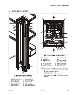
Page 105: ...PONENTS 3121222 JLG Lift 6 1 SECTION 6 MAST COMPONENTS 6 1 MAST COMPONENTS OVERVIEW Figure 6 1 Mast Components 1 Platform Assembly 2 Tool Tray 3 Mast Cover Plate 4 Mast Assembly 5 AC Power Receptacle 6 Manual Storage Box ...

Page 106: ... not use a screw with the threaded portion longer than 1 2 in 12mm whenattachingtothesideofthemast MastCoverPlateInstallation 1 Mast Cover Plate 2 Rivet Nuts 3 Top of Mast Assembly ACReceptacleBox Installation 1 AC Voltage Receptacle Box Components 2 Attach Screws 3 Platform Mast Assembly NOTE See AC POWER RECEPTACLES AND WIRING PLATFORM CE SPEC MACHINES ONLY on page 9 39 for receptacle wiring con...

Page 107: ... Top View 1 Front of Machine 2 Rear of Machine 3 Platform Outer Mast Section 4 Outer Mid Mast Section 5 Inner Mid Mast Section 6 Mount Inner Mast Section 7 Hydraulic Cylinder Compart ment 8 Power Trak Compartment 9 Cylinder 1 Bleeder Valve 10 Cylinder 2 Bleeder Valve 11 Cylinder 3 Bleeder Valve 12 Corner Slide Pads a NOTE a Always mount slide pads with the groove oriented to the side of the mast n...

Page 108: ... out of the mast section until the plat form is lifted later and the upper slide pads on outer mid section pushes them out 5 Disconnect the platform control box main har ness connector from the bottom of the platform control box and allow to hang loose for now Remove the platform control box from the plat form 6 Remove the AC outlet receptacle box from the outside of the outer mast section Allow t...

Page 109: ...o a suitable area for later assembly Platform Installation 1 Using an overhead crane with lifting strap lift the platform assembly up over the main mast assembly 2 Before lowering the platform assembly onto the mast be certain the electrical cables for the AC receptacle box and platform control station are Figure 6 5 Platform to Mast Installation 1 Platform Outer Mast Section Lower Slide Pad Locat...

Page 110: ...ng the two 2 bolts and nuts to the lug at the top of the platform mast section See Figure 6 5 Item 2 7 Route the electrical cables down the right side of the mast section and reinstall the metal cable cover using the two 2 screws previously removed 8 Reattach the AC receptacle box to the side of the mast and install the platform control box to the platform control box mounting plate Attach the pla...

Page 111: ... cable to be disconnected and feed down through the mast with the power trak 4 If removing the power trak from the mast use the following steps See illustration above a Remove the attach screws from the power trak guide bracket b Push the power track and cables down into the mast past the hanger bracket slot in the side of the mast 5 At the top of the mast carefully open the bleeder valve on the t...

Page 112: ...nder anchor cross bars 2 Using suitable lifting equipment and strap slide the cylinder assembly out the bottom of the mast assembly place on a suitable workbench Figure 6 9 Hydraulic Cylinder Connections Removal 1 Lift Down Valve Selenoid Har ness 2 Extend and Return Hydraulic Lines a NOTE a Open hydraulic lines carefully have a container ready to catch draining oil capportsandlines immediatelyonc...

Page 113: ...slide pads with the groove oriented to the side of the mast not the front or rear for clear ance of the pad mounting rivets during opera tion See Figure 6 3 The slide pads are available in two thicknesses JLG P N 1001092165 9 7 mm thick round notch on ends JLG P N 4700042 8 7 mm thick NO round notch on end Always use the 1001092165 slide pad unless mast tube clearances prevent installation 2 Slide...

Page 114: ... take the top end of the power trak assembly and feed it into the power trak compartment on the front side of the mast assembly 5 Lower mast assembly down or pull cylinder rod out of cylinder 1 and align the holes in the bot tom of the rod assembly with the holes in the base frame Secure using the proper bolts apply Loctite 242 to the threads of the rod attach bolts on final assembly See Figure 6 ...

Page 115: ...2in 50mm Mast Lower End Installation Original Design 1 Control Cable P Clamp a 2 RouteCableThroughNotchin Mast Baffle Plate 3 Left Front Mast Mounting Bolt b NOTE a Install clamp between washer and nut of the right rear mast mounting bolt b An extra washer may be required to space the screw away from the RED manualdescentbuttonontheliftcylinder Torquemastmountingboltsto62 ft lbs 88Nm tighteninanX ...

Page 116: ... in the catch container 7 Set the platform control station to platform lift mode and push the joystick to lift the platform Do not allow the platform to lift to far off the stowed position re lower and lift again if neces sary 8 Watch the bleeder tube when a constant flow of oil no bubbles is visible close the bleeder valve 9 Remove the bleeder tube and line wrench and move to the next cylinder in...

Page 117: ...erview The hydraulic cylinder for this machine is a multi stage three cylinder design Figure 6 15 1230ES Lift Cylinder Internal Components Top End 1 Cyl 3 Gland 2 Cyl 3 Wiper Seal 3 Cyl 3 Main Seal 4 Cyl 3 Gland Wire Retaining Ring 5 Cyl 3 Gland O Ring Seal 6 Cyl 1 End Cap a 7 Cyl 1 Piston Retaining Ring 8 Cyl 1 Piston 9 Cyl 1 Piston Guide Ring 10 Cyl 1 Piston Damping Spring 11 Cyl 1 Rod Guide Spa...

Page 118: ...ch Cap c d 13 Cyl 2 Cap O Ring Seal 14 Cyl 2 Joint O Ring Seals 15 Cyl 2 Rod Wiper Seal 16 Cyl 2 Gland d 17 Cyl 2 Main Seal 18 Cyl 2 Gland Wire Retaining Ring 19 Cyl 2 O Ring 20 Cyl 3 Barrel End Cap e 21 Cyl 3 Piston Retaining Ring 22 Cyl 3 Piston 23 Cyl 3 Piston Damping Spring 24 Cyl 3 Piston Guide Ring NOTE a Smallorificeratedat4GPM 115Liters minute b Theproportionalselenoidcoilhasa28ohmrating c...

Page 119: ...he cylinder rod to protect it from damage then clamp the cylinder rod into a vise or device to keep it from turning while removing the valve block assembly 2 Using the proper size wrench approx 55mm 2 165 turn the valve block assembly counter clockwise to remove it from the end of the cylin der rod Cylinder 2 and 3 Removal from Stack 1 Using the proper size wrench 44mm 1 732 remove cylinder 2 rod ...

Page 120: ...ow the end of the cylinder barrel and carefully pull the gland out of the end of the cylinder barrel Allow any hydraulic oil to drain EXTREME CARE SHOULD BE TAKEN WHEN REMOVING THE CYLINDER ROD HEAD AND PISTON AVOID PULLING THE ROD OFF CENTER WHICH COULD CAUSE DAMAGE TO THE PISTON AND CYLINDER BAR REL SURFACES 5 Carefully slide the rod assembly out of the cylin der barrel and place on a clean surf...

Page 121: ...s the piston should be replaced Tube Assembly Visually inspect the inside bore for scratches and pits There should be no scratches or pits deep enough to catch the fingernail Scratches that catch the fingernail but are less than 0 5 inch long and primarily in the circumferential direction are acceptable provided they cannot cut the pis ton seal The roughness of the bore should be between 10 and 20...

Page 122: ... CHIPPING OR OTHERWISE WILL CAUSE EVENTUAL GLAND SEAL FAILURE THE CYLINDER ROD MUST BE REPLACED IF DAMAGED 1 Lubricate and place a new o ring in the groove on the tapered end of cylinder rod 1 NOTE The cylinder rod and valve body threads need to be clean and free of oil when the valve body is assem bled to the cylinder assembly so the loctite applied to the cylinder rod threads will set properly 2...

Page 123: ...SC then you will be able to scroll using the right and left arrow keys to select a different menu item The top level menus are as follows Also see menu flow charts Figure 7 1 and Figure 7 2 HELP DIAGNOSTICS ACCESS LEVEL PERSONALITIES See Table 7 3 on Page 7 11 MACHINE SETUP See Table 7 1 on Page 7 9 ACTIVATE TESTS CALIBRATION If you press ENTER at the HELP PRESS ENTER display and a fault is presen...

Page 124: ...annot be changed until you enter a pass word to advance to a lower level This ensures that a set ting cannot be accidentally altered To change the access level the correct password must be entered To enter the password scroll to the ACCESS LEVEL menu For example MENU ACCESS LEVEL 2 Press ENTER to select the ACCESS LEVEL menu Using the UP or DOWN arrow keys enter the first digit of the password 3 T...

Page 125: ...ol lowing pages in this Service Manual for the default settings Password 33271 will give you access to level 1 which will permit you to change all machine personality and or machine setup settings CHANGING THESE SETTINGS MAY ADVERSELY AFFECT THE PERFOR MANCE OF YOUR MACHINE IT IS A GOOD PRACTICE TO AVOID PRESSURE WASHING ELECTRICAL ELECTRONIC COMPONENTS SHOULD PRESSURE WASHING BE UTI LIZED TO WASH...

Page 126: ...WD MAX 1 20V ACCELERATOR REV MIN 2 75V ACCELERATOR REV MAX 3 80V DRIVE ACCEL 0 1 5 0 S DRIVE DECEL 0 1 10 0 S DRIVE MINIMUM 0 25 DRIVE MAXIMUM 0 100 DRIVE ELEV MAX 0 25 LIFT ACCEL 0 1 5 0S GROUND HORN 107DB LOAD ACC Y 0 200KG LOAD OVR DBNCE 3 0S LOAD OVR HOLD 5 0S LEVEL VEHICLE YES ENTER NO ESC SET ELEV SENSOR YES ENTER NO ESC LIFT DECEL 0 1 1 0S LIFT UP MIN 0 50 LIFT UP MAX 1 100 LIFT UP MIN 0 60...

Page 127: ... GM SW P VERSIONS GM HW REV VERSIONS GM SN VERSIONS PM SW P VERSIONS PM HW REV VERSIONS PM SN ACTIVATE TEST YES ENTER NO ESC RUN SYSTEM TEST TEST VAVLES RUN SYS TEST 3 TEST GND SW RUN SYS TEST 4 TEST PLT SW RUN SYS TEST 3 TEST OVLD ALRM RUN SYS TEST 4 TEST LEDS ALRM RUN SYSTEM TEST TEST COMPLETE RUN SYS TEST 4 TEST PROP CNTRL RUN SYSTEM TEST LT STEER RUN SYSTEM TEST RT STEER RUN SYSTEM TEST CLOSE ...

Page 128: ...SECTION 7 JLG CONTROL SYSTEM 7 6 JLG Lift 3121222 Figure 7 3 Analyzer Menu Flow Chart Sheet 1 of 3 1001096495 Machines Equipped with ZAPI 1001092456 Power Module Only ...

Page 129: ...SECTION 7 JLG CONTROL SYSTEM 3121222 JLG Lift 7 7 Figure 7 4 Analyzer Menu Flow Chart Sheet 2 of 3 1001096495 Machines Equipped with ZAPI 1001092456 Power Module Only ...

Page 130: ...SECTION 7 JLG CONTROL SYSTEM 7 8 JLG Lift 3121222 Figure 7 5 Analyzer Menu Flow Chart Sheet 3 of 3 1001096495 Machines Equipped with ZAPI 1001092456 Power Module Only ...

Page 131: ...TEDwhilevehicleischarging RequiredforCE 0 0 0 0 0 0 6 Ground Alarm 0 1 2 NOTINSTALLED VehiclealarmwillfunctionforArmGuard ifenabled Overload ifLSS enabled andasahorn DESCENT VehiclealarmwillfunctionforArmGuard ifenabled Overload ifLSS enabled asahornandduringLiftDownmotion MOTION VehiclealarmwillfunctionforArmGuard ifenabled Overload ifLSS enabled asahornandduringDriveandLiftmotion 2 2 2 0 2 2 7 L...

Page 132: ...ng DRIVEANDLIFTUP Driveandliftupmotionsarepreventedwhilevehicleischarging RequiredforCE 0 0 0 0 0 0 6 Ground Alarm 0 1 2 NOTINSTALLED VehiclealarmwillfunctionforArmGuard ifenabled Overload ifLSS enabled andasahorn DESCENT VehiclealarmwillfunctionforArmGuard ifenabled Overload ifLSSenabled asahornandduringLiftDownmotion MOTION VehiclealarmwillfunctionforArmGuard ifenabled Overload ifLSSenabled asah...

Page 133: ...R STATIC 0 100 100 DRIVE 0 100 60 ACCELERATOR FWDMIN 2 20 2 40V 2 25 FWDMAX 1 00 1 50V 1 20 REVMIN 2 60 2 80V 2 75 REVMAX 3 50 4 00V 3 80 GROUND HORN 87 107dB 107 ALARM 87 107dB 87 LOAD ACCY 0 200Kg N A OVRDBNCE 0 0 5 0Sec N A OVRHOLD 0 0 5 0Sec N A Table 7 4 Machine Personality Adjustment 1001115627 B Machines Equipped with ZAPI 1001092456 Power Module Function Adjustment Range 1230ES Factory Set...

Page 134: ...heck the box s mounting surface for levelness b Tilt sensor mounting on machine or wedged crooked in control box If the machine mounting grade appears acceptable remove and open the Ground Control box carefully Observe whether the tilt sensor is properly seated c Tilt sensor has developed an offset shift Remove the tilt sensor from the Ground Con trol box but keep both the tilt sensor and Ground C...

Page 135: ...he machine to these points If a level sur face can not be found flat shims or plates may be place under the wheels to create a level plane for the wheels In determining the existing tilt angle read the angle on the Analyzer under DIAGNOSTICS SYSTEM Do not place a hand held level on the machine to determine whether the machine is level and lifting to the appropriate height Such a measurement will l...

Page 136: ...a tion 3 Go to Access Level 1 and scroll through to CALI BRATION 4 Under Calibrations go to SET ELEV SENSOR 5 Press enter for Yes and the Elevation Sensor will set NOTE Check the elevation sensor by lifting the scissor arms from the platform and driving until the drive speed cuts back Refer to the Maximum High Drive Cut Out Height table in section 1 of this manual for proper speed cut out height ...

Page 137: ...ven a three digit identifier number pre ceded with an X for identifying and locating the specific connector on the machine See Section 9 8 X CONNECTOR ID INDEX for description of X connectors and Figure 9 12 on page 9 20 and Figure 9 13 on page 9 21 for location of X connectors on the machine Example of X connector usage nomenclature X006 21 refers to terminal 21 pin and socket of connector X006 X...

Page 138: ...336 LIFT DN OPEN CIRCUIT 6 10 337 STEER LEFT SHORT TO BATTERY 6 10 338 STEER LEFT OPEN CIRCUIT 6 10 339 STEER RIGHT SHORT TO BATTERY 6 10 3310 STEER RIGHT OPEN CIRCUIT 6 10 3311 GROUND ALARM SHORT TO BATTERY 6 10 3312 LEFT BRAKE SHORT TO BATTERY 6 10 3313 RIGHT BRAKE SHORT TO BATTERY 6 10 3314 LEFT BRAKE OPEN CIRCUIT 6 11 3315 RIGHT BRAKE OPEN CIRCUIT 6 11 33297 LEFT BRAKE SHORT TO GROUND 6 11 332...

Page 139: ...ON 6 17 994 LSS INTERNAL ERROR DRDY MISSING FROM A D 6 17 995 POWER MODULE FAILURE PERSONALITY RANGE ERROR 6 17 996 POWER MODULE FAILURE INTERNAL ERROR 6 18 997 POWER MODULE FAILURE CHECK POWER CIRCUITS OR MOSFET SHORT CIRCUIT 6 18 998 EEPROM FAILURE CHECK ALL SETTINGS 6 18 999 FUNCTION LOCKED OUT POWER MODULE SOFTWARE VERSION IMPROPER 6 18 9910 FUNCTION LOCKED OUT PLATFORM MODULE SOFTWARE VERSION...

Page 140: ...MODULE FAILURE INTERNAL ERROR 9 20 99145 POWER MODULE FAILURE INTERNAL ERROR 9 21 99146 POWER MODULE FAILURE INTERNAL ERROR 9 21 99147 POWER MODULE FAILURE INTERNAL ERROR 9 21 99148 POWER MODULE FAILURE INTERNAL ERROR 9 21 99149 POWER MODULE FAILURE INTERNAL ERROR 9 21 ...

Page 141: ...n 5 2 004 DRIVINGATCUTBACK ABOVEELEVATION Theplatformiselevatedandthe machineisdriving Fully stow the platform Check that the elevation angle sensor is securely mounted Check that the pothole protection switches are securely mounted Check the lift drive switch Backprobing ground board J1 18 should show about 0 volts Backprobing ground board J1 10 should show about 0 volts Check function of elevati...

Page 142: ...ourswithoutactivity thecontrolsystementersalow powerstatetopreservebattery charge Normal operation should resume after a power cycle Check batteries charge condition etc 009 DRIVEPREVENTED ELE VATEDABOVEDRIVE CUTOUTHEIGHT Theplatformiselevatedabove thecalibratedcutoutheight Check that the elevation angle sensor is securely mounted Check the ANALYZER MACHINE SETUP MARKET configuration If MARKET is ...

Page 143: ...1 16 Replace platform board 226 ACCELERATORFAULTY WIPEROUTOFRANGE Thejoysticksignalisoutsidethe acceptablerangeof0 50V 4 5V orisunstable Center joystick and check to see if a power cycle will clear DTC Check the joystick signal and its wiring The joystick input 5V is from the platform board terminal J1 5 its output 2 5V with joystick at center to the platform board terminal J1 6 and its ground 0V ...

Page 144: ...to ground board terminals J2 6 up J2 7 down Replace ground board 233 FUNCTIONPROBLEM BRAKERELEASEPERMA NENTLYSELECTED Themanualbrakereleaseswitch wasclosedduringpower up Check if the brake release switch is obstructed or jammed Checkthebrakereleaseswitch signalandwiringtothegroundboard The brake release switch input 24V is from ground board terminal J1 19 and its output 24V when closed is to groun...

Page 145: ... pro tection mechanisms Check that the PHP switches are securely mounted Adjust pot hole protection switches Check the pothole protection switches signal and wiring to the ground board The left pot hole protection switch input 24V is from ground board terminal J1 9 and its output 24V when deployed is to ground board terminal J1 10 The right pot hole protection switch input 24V is from groundboard ...

Page 146: ...oid resistance should measure about 52 Ohms Check contactor solenoid wiring to power module 12 position connector terminal 8 and ground board terminal J1 19 Checkthatpower module12positionconnectorterminal8goes from 24V to near 0V while contactor should be closing If this happens replace con tactor Replace the line contactor 312 CONTACTORDRIVER PERMANENTLYOFF Thepowermoduleslinecontac tordrivecirc...

Page 147: ...wiring for physical damage Replace ground board 335 LIFTDNSHORTTOBAT TERY Thegroundboarddetected voltagewhiletheliftdownsole noidwascommandedoff Check ANALYZER MACHINE SETUP ELEV PROX is set to NOT INSTALLED Check for continuity through this circuit The lift down solenoid resistance should measure about 20 Ohms The lift down solenoid is powered PWM by ground board J1 26 and its ground is to ground...

Page 148: ...bout 20 Ohms Inspect the wiring for physical damage Replace ground board 3313 RIGHTBRAKESHORTTO BATTERY Voltagewasdetectedonthe rightbrakesolenoidwhenthe groundboardoutputwascom mandedoffduringpower up Check for continuity through this circuit Brake solenoid resistance should measure about 20 Ohms The right brake is powered with 24V from ground board J1 24 and its ground is to ground board J1 30 3...

Page 149: ...tus LED ON 33407 LIFTDNVALVE SHORTTO GROUND LiftUpandDownPrevented Excessive current flow to the Lift Down Solenoid was detected J2 16 NDV ZAPI HEALTH Status LED ON 4 2 Thermal Limit SOA DTC FAULT MESSAGE DESCRIPTION CHECK 421 POWERMODULETOO HOT PLEASEWAIT Thepowermodulehasreached thermalcutout Power down and allow to cool Do not operate in ambients over 140 F 60 C Check for jammed or obstructed d...

Page 150: ...or an improper wire harness connection Drive Steer and Lift Prevented ZAPI HEALTH Status LED ON 4421 LOGICSUPPLYVOLTAGEOUTOF RANGE Thesystemmodulelogicsupply voltagewasmeasuredbythe powerPCBtobemorethan34V for10uS This may be caused by a loose battery terminal severely discharged bat teries damaged battery or an improper wire harness connection Drive Steer and Lift Prevented ZAPI HEALTH Status LED...

Page 151: ...to armstack passthru pin 7 should measure open circuit Disconnect ground board J1 and power module connector Ground board socket J1 31 to power module connector socket 10 should have continu ity Ground board socket J1 32 to power module connector socket 11 should have continuity Ground board socket J1 31 to J1 32 should mea sure open circuit Ground board socket J1 31 to J1 33 should measure open c...

Page 152: ...y causedbyastalled tractionmotoror power wir ing issue Alternately it could be an internal fault ZAPI HEALTH Status LED ON 773 CAPACITORBANKFAULT CHECK POWERCIRCUITS Drive Steer andLiftPrevented There is an internal or external fault that prevents the System Module s capacitor bank from charging The System Module detected that the VMN of the pump and traction has not increased more than 1 3V in 10...

Page 153: ...er andLiftPrevented Whilesteeringorliftingup thevoltagemeasuredattheSystem Module s P terminal did not agree with the predicted value for at least 1000mS This issue may be caused by an open circuit of the pump wiring BF2 and P terminals or an internal fault Pump feedback does not increase more than 1 3V Pump feedback is less than 20 Battery Voltage Battery Voltage pump feedback is greater than 4V ...

Page 154: ...SINTERNALERROR DRDYMISSINGFROMA D Aproblemhasbeendetected withtheloadsensesystem Refer to Section 2 3 Troubleshooting in the LSS manual 3124288 995 POWERMODULEFAIL URE PERSONALITY RANGEERROR Thepowermoduledetectedan out of rangeorcorruptperson alitysetting Record all personality settings in ANALYZER PERSONALITIES and ANA LYZER MACHINE SETUP Reset control system personalities to default settings by...

Page 155: ... still exists replace System Module ZAPI HEALTH Status LED FLASHING 9953 POWERMODULEFAILURE INTERNALERROR Drive Steer LiftPrevented The System Module s field power circuitry is driven without enable from the interface PCB for 100mS Cycle machine if error still exists replace System Module ZAPI HEALTH Status LED FLASHING 9954 POWERMODULEFAILURE INTERNALERROR Drive Steer LiftPrevented The System Mod...

Page 156: ... stored in the interface PCB Cycle machine if error still exists replace System Module ZAPI HEALTH Status LED ON 9971 POWERMODULEFAILURE INTERNALERROR Drive Steer LiftPrevented The System Module s MC EB valve activation pin is shorted This is an internal fault Cycle machine if error still exists replace System Module ZAPI HEALTH Status LED FLASHING 99143 POWERMODULEFAILURE INTERNALERROR Drive Stee...

Page 157: ...does not match the input state Cycle machine if error still exists replace System Module ZAPI HEALTH Status LED FLASHING 99149 POWERMODULEFAILURE INTERNALERROR Drive Steer LiftPrevented The System Module encountered an unexpected software issue Cycle machine if error still exists replace System Module ZAPI HEALTH Status LED FLASHING 9 9 Hardware DTC FAULT MESSAGE DESCRIPTION CHECK ...

Page 158: ...SECTION 8 DIAGNOSTIC TROUBLE CODES 8 22 JLG Lift 3121222 NOTES ...

Page 159: ...ge source Backprobing To backprobe means to take the measurement by accessing a connector s contact on the same side as the wires the back of the connector Readings can be done while maintaining circuit continuity this way If the connector is the sealed type great care must be taken to avoid damaging the seal around the wire It is best to use probes or probe tips specifically designed for this tec...

Page 160: ...correct range See multimeter s operation manual Use firm contact with meter leads First test meter and leads by touching leads together Resistance should read a short circuit very low resistance Circuit power must be turned OFF before testing resistance Disconnect component from circuit before testing If meter is not auto ranging set it to the correct range See multimeter s operation manual Use fi...

Page 161: ...FF before testing continuity Disconnect component from circuit before testing Use firm contact with meter leads First test meter and leads by touching leads together Meter should produce an audible alarm indicating continuity Set up the meter for the expected current range Be sure to connect the meter leads to the correct jacks for the current range you have selected If meter is not auto ranging s...

Page 162: ... wire under test or are within reach of the jumper 1 Disconnect all connections associated with the wire under test and the two additional wires If harness is not com pletely isolated disconnect battery terminals also as a precaution 2 Measure continuity between all three wires the wire under test wire 1 and wire 2 These should be open If not repair the shorted wires or replace the harness 3 On on...

Page 163: ...ches Limit switches are used to control movement or indicate position Mechanical limit switches are just like manually oper ated switches except that the moving object operates the switch These switches can be tested the same way as a stan dard switch by manually operating the sensing arm Another type of limit switch used by JLG is the inductive proximity switch also referred to as a prox switch I...

Page 164: ...positive side of the power source and the load This switch is called a high side switch The switch supplies the power to the load When a switch is wired between the negative side of the power source and the load it is a low side switch The switch provides the ground to the load A low side switch will allow voltage to be present on the load No power is applied because the switch is stopping current...

Page 165: ...d low level conductivity silicone dielectric grease must be packed completely around male and female pins on the inside of the connector after the mating of the housing to the header This is easily achieved by using a syringe to fill the header with silicone dielectric compound to a point just above the top of the male pins inside the header When assembling the housing to the header it is possible...

Page 166: ...s it will go See Connector Assembly Fig ure 2 2 Pull back on the contact wire with a force of 1 or 2 lbs to be sure the retention fingers are holding the contact See Connector Assembly Figure 2 3 After all required contacts have been inserted the wedge lock must be closed to its locked position Release the lock ing latches by squeezing them inward See Connector Assembly Figure 3 4 Slide the wedge ...

Page 167: ...SECTION 9 GENERAL ELECTRICAL INFORMATION SCHEMATICS 3121222 JLG Lift 9 9 Connector Assembly Figure 3 Connector Assembly Figure 4 ...

Page 168: ...ock has slotted openings in the forward or mating end These slots accommodate circuit testing in the field by using a flat probe such as a pocket knife DO NOT use a sharp point such as an ice pick Service Voltage Reading DO NOT PIERCE WIRE INSULATION TO TAKE VOLTAGE READINGS It has been common practice in electrical troubleshooting to probe wires by piercing the insulation with a sharp point This ...

Page 169: ...SECTION 9 GENERAL ELECTRICAL INFORMATION SCHEMATICS 3121222 JLG Lift 9 11 Figure 9 5 Connector Installation ...

Page 170: ...ed Thy may go in either way NOTE The receptacle is shown use the same procedure for plug DT DTP Series Disassembly Figure 9 7 DT DTP Contact Removal 1 Remove wedgelock using needlenose pliers or a hook shaped wire to pull wedge straight out 2 To remove the contacts gently pull wire backwards while at the same time releasing the locking finger by moving it away from the contact with a screwdriver 3...

Page 171: ...t of connector Figure 9 11 HD HDP Unlocking Contacts NOTE Do Not twist or insert tool at an angle 9 6 X CONNECTOR REFERENCES Throughout this Service Manual electrical connectors are given a three digit identifier number preceded with an X for identifying and locating the specific connector See Section 9 8 X CONNECTOR ID INDEX for description of X connectors and Figure 9 12 on page 9 20 and Figure ...

Page 172: ... 9 1 Connector Loading Diagrams ID Description Diagram AMP02P Amp2positionplug AMP02R Amp2positionreceptacle AMPC02P AmpCommercial2position plug AMP04P Amp4positionplug AMP04R Amp4positionreceptacle AMP09P Amp9positionplug CXA08P Conxall8positionplug 1 2 2 1 1 2 1 2 4 3 2 1 4 3 1 1 7 3 9 2 8 4 6 1 7 6 5 4 3 2 8 ...

Page 173: ...alum Receptacle DRC40P Deutsch40positionplug DT02P Deutsch2positionDTseries plug DT02R Deutsch2positionDTseries receptacle DT03P Deutsch3positionDTseries plug Table 9 1 Connector Loading Diagrams Continued ID Description Diagram A B C D E F G H J K L M N P REA RVIEW A B C D E F G H J K L M N P REA RVIEW 1 40 10 6 5 11 21 31 35 36 30 20 1 2 2 1 B C A ...

Page 174: ...08AP Deutsch8positionDTseries plugwithAkeys DT08AR Deutsch8positionDTseries receptaclewithAkeys DTM12AP Deutsch12positionDT seriesminiplugwithAkey DTM12BP Deutsch12positionDT seriesminiplugwithBkey E06P EatonToggleSwitch Table 9 1 Connector Loading Diagrams Continued ID Description Diagram 7 8 9 10 11 12 6 5 4 3 2 1 7 8 9 10 11 12 6 5 4 3 2 1 1 2 3 4 5 6 ...

Page 175: ...009 RHPotholeSwitch X010 GroundPassthru AMP04P AMP04R X011 DiagnosticPort AMP04R X012 BrakeReleasePower X013 BrakeReleaseIgn X014 Beacon DT02R X017 ArmStackPassthru DT08AR DT08AP X018 ChargerInterlock AMP02P AMP02R X019 ChargerPlug X020 Charger DT06AP DT06R X021 Battery X022 GroundAlarm DT03P X023 LHPotholeSwitch X024 LeftBrake DT02R DT02P X025 RightBrake DT02R DT02P X026 Contactor DT02R X027 Powe...

Page 176: ...ormBox DHD14P DHD14R X047 PlatformE StopOut X048 PlatformE StopIn X049 Joystick AMP09P X050 PlatformModuleJ1 MMF16P X051 PlatformLiftDriveSwitch MMF03P X052 PlatformAlarm X053 PlatformAlarm X054 PlatformHornSwitch X056 InverterSwitchOut X057 InverterSwitchIn X058 ContactorSupply X059 ContactorOut X060 PowerModuleB X061 PowerModuleF1 X062 PowerModuleF2 X063 LeftMotorPowerModM1 X064 PowerModuleP X06...

Page 177: ...Inverter X089 Inverter X090 RightWheelBrakeSolenoid AMPC02P X091 LeftWheelBrakeSolenoid AMPC02P X092 RightWheel X093 LeftWheel X094 RightWheel X095 LeftWheel X096 RightWheelFieldfromF1 X097 LeftWheelFieldfromF2 X098 RightWheelFieldCommon X099 LeftWheelFieldCommon X104 1230FootswitchChassis DT08AP X105 1230FootswitchPlatform DT08AR X106 1230FootswitchJ1 DTM12BP X107 1230FootswitchJ2 DTM12AP X108 12...

Page 178: ...X078 X079 X088 X091 X093 X095 X097 X099 X047 X048 X049 X052 X053 X050 X051 X052 X046 X026 X058 X059 X018 X019 X020 X082 X087 X089 X110 X111 X112 X008 X071 X072 X073 X074 X075 X086 X029 X060 X016 X062 X063 X064 X065 X066 X083 X084 X085 X104 X105 X106 X107 X108 X014 X009 X023 X022 X056 X057 X012 X013 SEEGROUND MODULEDETAIL X090 X092 X094 X096 X098 X041 X042 X043 X069 X070 X109 X011 X024 X025 X080 X0...

Page 179: ...INFORMATION SCHEMATICS 3121222 JLG Lift 9 21 Figure 9 13 1230ES Location of Component X Connectors on Ground Control Module X040 X003 X010 X029 X030 X033 X034 X028 X003 X002 X001 X038 X039 X036 2 W IRES 1 W IRE X035 X037 X031 X032 ...

Page 180: ...MATICS Figure 9 14 1230ES Overview of Electrical System Components 1600346 Drive Module POTHOLEPROTECTION SW ITCHES ALARM BEA CONLIGHT PLA TFORMCONSOLE BOX GROUNDCONTROL BOX PLA TFORM RECEPTACLE MODULE JA P A NESE SPEC BRA KE DISCONNECT SW ITCH DRIVEMOTORS PUMP MOTOR TA NK J1 J2 DIA GNOSTIC A NAL YZER R L ...

Page 181: ...S 3121222 JLG Lift 9 23 Figure 9 14 1230ES Overview of Electrical System Components 1600346 Drive Module CONTACTOR RELA Y PROXIMITY SENSOR POW ERMODULE LIFT CYLINDER BA TTERY CHARGER BA TTERY CHARGER INVERTER INVERTER POWER SWITCH TOAC POWER BA TTERIES ...

Page 182: ...gure 9 15 1230ES Overview of Electrical System Components 1001092456 Drive Module POTHOLEPROTECTION SW ITCHES A LA RM BEA CONLIGHT HA NDHELDA NA L YZERCONNECTION GROUND CONTROL BOX PLA TFORM RECEPTA CLE BRA KE DISCONNECT SW ITCH DRIVEMOTORS PUMP MOTOR TANK PLA TFORMCONSOLE BOX ...

Page 183: ...5 Figure 9 15 1230ES Overview of Electrical System Components 1001092456 Drive Module RELA Y BA TTERY CHARGER BA TTERY CHARGER INVERTER INVERTER POWER SWITCH TO AC POWER PROXIMITY SENSOR LIFT CYLINDER CONTA CTOR RELA Y BA TTERIES DRIVE CONTROLLER BF1 BF2 B J1 F1 J2 F2 B T P ...

Page 184: ...SECTION 9 GENERAL ELECTRICAL INFORMATION SCHEMATICS 9 26 JLG Lift 3121222 Figure 9 16 Electrical Schematic Machines with 1600346 Drive Module ...

Page 185: ...SECTION 9 GENERAL ELECTRICAL INFORMATION SCHEMATICS 3121222 JLG Lift 9 27 Figure 9 16 Electrical Schematic Machines with 1600346 Drive Module 1870188_E ...

Page 186: ...SECTION 9 GENERAL ELECTRICAL INFORMATION SCHEMATICS 9 28 JLG Lift 3121222 Figure 9 17 Electrical Schematic Machines with 1001092546 Drive Module ...

Page 187: ...SECTION 9 GENERAL ELECTRICAL INFORMATION SCHEMATICS 3121222 JLG Lift 9 29 Figure 9 17 Electrical Schematic Machines with 1001092546 Drive Module 1001114879_F 1 ...

Page 188: ...SECTION 9 GENERAL ELECTRICAL INFORMATION SCHEMATICS 9 30 JLG Lift 3121222 Figure 9 18 Electrical Schematic Machines with 1001092546 Drive Module ...

Page 189: ...SECTION 9 GENERAL ELECTRICAL INFORMATION SCHEMATICS 3121222 JLG Lift 9 31 Figure 9 17 Electrical Schematic Machines with 1001092546 Drive Module 1001114879_F 2 ...

Page 190: ...SECTION 9 GENERAL ELECTRICAL INFORMATION SCHEMATICS 9 32 JLG Lift 3121222 Figure 9 19 Electrical Schematic Ground Control Module Machines with 1001092546 Drive Module 1001114879_F 3 ...

Page 191: ...utput Comm 13 CANBusShield PowerOutput 0 14 NotUsed 15 ElevationProxSwitch Input 5 16 Ground PowerOutput 0 17 NotUsed 18 RightPHPSwitch Input Vbatt 19 Ignition PowerOutput Vbatt 20 BrakeReleaseSwtich Input Vbatt 21 SteerLeftCoil Output Vbatt 22 SteerRightCoil Output Vbatt 23 RightBrakeRelease Output Vbatt 24 LeftBrakeRelease Output Vbatt 25 LiftUpCoil Output Vbatt 26 LiftDownCoil Output PWM 27 Gro...

Page 192: ...xis PWM Input 12 4 Ground PowerOutput 0 Table 9 6 Platform Board J1 Connector X050 Pin Function Type Range V 1 MasterIgnition PowerInput Vbatt 2 MasterGround PowerInput 0 3 CANBusHigh Input Output Comm 4 CANBusLow Input Output Comm 5 JoystickPowerSupply PowerOutput 5 6 JoystickSignal Input 5 7 Ground PowerOutput 0 8 TriggerSwitch Input Vbatt 9 LiftSelectSwitch ActiveLow Input Vbatt 10 DriveSelectS...

Page 193: ...Used 4 NotUsed 5 NotUsed 6 NotUsed 7 HornSwitch ActiveLow Input Vbatt Table 9 9 Power Module Connector X027 1600346 Power Module Pin Function Type Range V 1 Ignition PowerInput Vbatt 2 NotUsed 3 NotUsed 4 NotUsed 5 NotUsed 6 NotUsed 7 NotUsed 8 LineContactorHighSide PowerOutput Vbatt 9 NotUsed 10 CANBusHigh Input Output Comm 11 CANBusLow Input Output Comm 12 NotUsed ...

Page 194: ...nput 16 PositiveRotarySensorReference 5V Power Output 17 NegativeforRotarySensor Power Output 18 PositiveLeftPotholeSwitchReference Connectto BATT Power Output 19 PositiveRightPotholeSwitchReference Connectto BATT Power Output 20 RS 232Receive Serial Input 21 RS 232Transmit Serial Output 22 NegativeforAnalyzer Connectto B Power Output 23 SpareNegativeReference Connectto B Power Output 24 SpareDigi...

Page 195: ...Output 10 SwitchManualBrakeRelease High Sensing Digital Input 11 SpareDigitalInput High Sensing Digital Input 12 SpareDigitalInput High Sensing Digital Input 13 SpareDigitalInput High Sensing Digital Input 14 SpareNegativeAnalogReference Connectto B Power Output 15 CANbusShield Connectto B Power Output 16 NegativeLiftDownValve Low SideDriver Power Output 17 NegativeLiftUpSolenoidValve Low SideDriv...

Page 196: ...SECTION 9 GENERAL ELECTRICAL INFORMATION SCHEMATICS 9 38 JLG Lift 3121222 Figure 9 20 Battery Charger Inverter Electrical Connection Schematic ...

Page 197: ...SECTION 9 GENERAL ELECTRICAL INFORMATION SCHEMATICS 3121222 JLG Lift 9 39 9 12 AC POWER RECEPTACLES AND WIRING PLATFORM CE SPEC MACHINES ONLY ...

Page 198: ...SECTION 9 GENERAL ELECTRICAL INFORMATION SCHEMATICS 9 40 JLG Lift 3121222 ...

Page 199: ...SECTION 9 GENERAL ELECTRICAL INFORMATION SCHEMATICS 3121222 JLG Lift 9 41 ...

Page 200: ...SECTION 9 GENERAL ELECTRICAL INFORMATION SCHEMATICS 9 42 JLG Lift 3121222 ...

Page 201: ...SECTION 9 GENERAL ELECTRICAL INFORMATION SCHEMATICS 3121222 JLG Lift 9 43 9 13 HYDRAULIC SCHEMATIC Figure 9 21 Hydraulic Diagram 2792703_B ...

Page 202: ...SECTION 9 GENERAL ELECTRICAL INFORMATION SCHEMATICS 9 44 JLG Lift 3121222 NOTES ...

Page 203: ...AFTER HANDLING Battery posts terminals and related accessories contain lead and lead compounds chemicals known to the State of California to cause cancer and reproductive harm Batteries also contain other harmful chemicals known to the State of California ...

Page 204: ...ude Ihlpohl Germany 49 0 421 69350 0 49 0 421 69350 45 Email german parts jlg com JLG Equipment Services Ltd Rm 1107 Landmark North 39 Lung Sum Avenue Sheung Shui N T Hong Kong 852 2639 5783 852 2639 5797 JLG Industries Italia S R L Via Po 22 20010 Pregnana Milanese MI Italy 39 0 2 9359 5210 39 0 2 9359 5211 Email ricambi jlg com JLG EMEA B V Polaris Avenue 63 2132 JH Hoofdorf The Netherlands 31 0...

Reviews: