


SECTION 4 - BASE COMPONENTS
3121222
– JLG Lift –
4-17
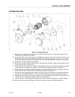
Drive Motor - Reassembly
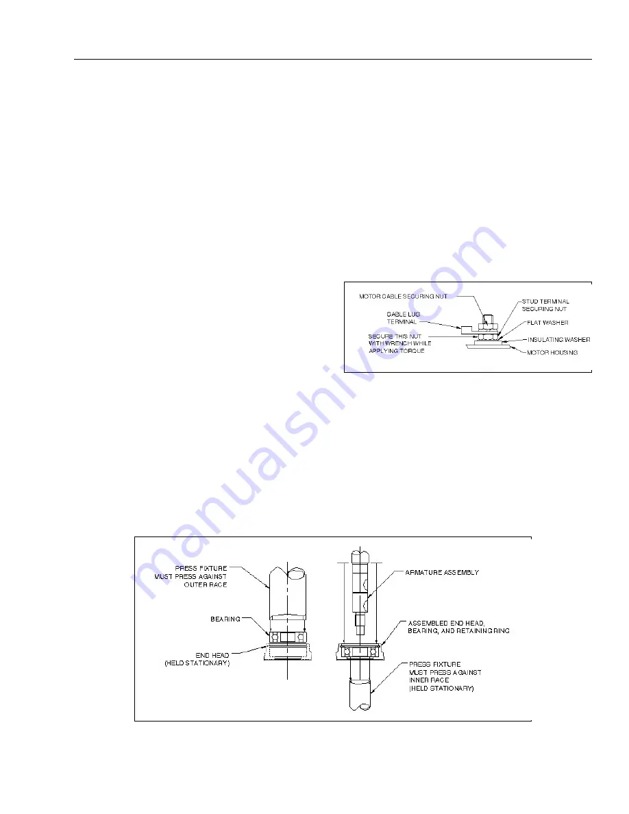
1.
After inspection and servicing, reassemble the
wiring in the commutator end head (9) as origi-
nally found. Ensure the wiring does not contact
metal parts and that it allows the brushes to
move unrestricted in the holders. Motor termi-
nals must be assembled as shown
. Torque bottom terminal nut to 110-140 in-lb
[12.4-15.8 N-m].
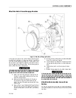
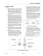
2.
After the motor has been disassembled, it is rec-
ommended that new bearings be installed
because bearings may have been damaged dur-
ing removal. Although the bearings may appear
and feel good, the bearing races could be "bri-
nelled"
(races or balls deformed)
and may exhibit
noise and vibration problems or fail within a rel-
atively short period of service. Press a new bear-
ing into the commutator end head, pressing on
the outer race only.
Replace the
snap ring (6) in the snap ring groove.
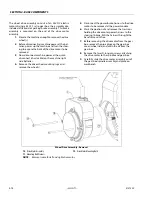
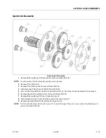
3.
Press the armature (2) commutator end into the
commutator end head and bearing assembly,
carefully supporting the inner-race of the bear-
ing.
.
4.
Carefully release the brush springs (4) allowing
the brushes to contact the commutator. Make
sure brush shunts do not interfere with spring
movement.
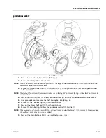
5.
Assemble the commutator end head to the
frame and field assembly (1) and tighten the
screws to 120-140 in-lb [13.6-15.8 N-m]. Make
sure to align the field connection with the notch
in the commutator end head. Seal wires where
they exit from commutator end head with a
small amount of RTV Silicone Sealant.
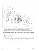
6.
Align wires from brake assembly (11) into notch
in friction disc (10). Install both items onto shaft
of motor aligning wires with groove in commu-
tator end head. Secure brake assembly to com-
mutator end head using 3 bolts and apply small
bead of RTV Silicone sealant around wires
between friction disc and commutator end head
and in notch in friction disc.
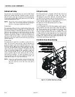
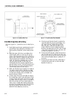
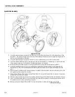
7.
Install wire harness (8) to motor by connecting
the field and brake connectors and securing the
armature terminals to the terminal studs. Refer
to Figure 4-7. for proper connections. Motor ter-
minals must be assembled as shown
. Always secure the bottom nut with a
wrench as you tighten the top nut. Torque top
nut to 90-110 in-lb [10.2-12.4 N-m].
8.
Remove manual release screws from brake
assembly. Apply new o-ring (13) and affix cover
(15) to motor using the 2 manual release screws.
A small dab of RTV Silicone sealant may be used
to secure the o-ring into the o-ring groove in the
cover to aid in assembly.
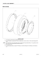
9.
Assemble strain relief bushing (14) around jacket
of wire harness and slide into slot in cover.
10.
Align cover plate (12) with groove in frame and
field and affix using 2 screws.
11.
Reinstall motor per instructions -
.
Figure 4-8. Motor Terminal Assembly
Figure 4-9. Bearing Replacement Procedure
Summary of Contents for 1230ES
Page 1: ...AS NZS Service and Maintenance Manual Model s 1230ES P N 3121222 June 22 2017 ...
Page 2: ...NOTES ...
Page 24: ...SECTION 1 MACHINE SPECIFICATIONS 1 12 JLG Lift 3121222 NOTES ...
Page 32: ...SECTION 2 GENERAL SERVICE INFORMATION 2 8 JLG Lift 3121222 NOTES ...
Page 78: ...SECTION 4 BASE COMPONENTS 4 40 JLG Lift 3121222 NOTES ...
Page 104: ...SECTION 5 CONTROL COMPONENTS 5 26 JLG Lift 3121222 NOTES ...
Page 158: ...SECTION 8 DIAGNOSTIC TROUBLE CODES 8 22 JLG Lift 3121222 NOTES ...
Page 198: ...SECTION 9 GENERAL ELECTRICAL INFORMATION SCHEMATICS 9 40 JLG Lift 3121222 ...
Page 199: ...SECTION 9 GENERAL ELECTRICAL INFORMATION SCHEMATICS 3121222 JLG Lift 9 41 ...
Page 200: ...SECTION 9 GENERAL ELECTRICAL INFORMATION SCHEMATICS 9 42 JLG Lift 3121222 ...
Page 202: ...SECTION 9 GENERAL ELECTRICAL INFORMATION SCHEMATICS 9 44 JLG Lift 3121222 NOTES ...


