Jetter AG
Electrical connection | 6
User Manual – JetControl 365MC
43 / 148
6.3.2 Configuration in JetSym
A simple example is used to illustrate the configuration in JetSym. Connect the
JX3-DIO16 expansion module as second module to a JC-365MC controller.
In a minimum program, a flashing light has been programmed. Output 9 of the
JX3-DIO16 is set and then reset.
Configuration
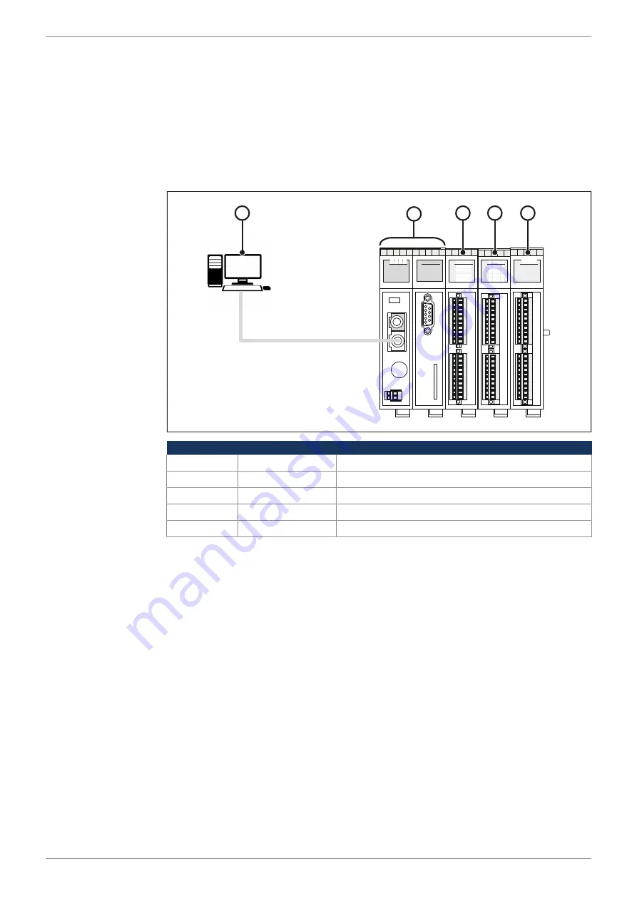
This example is based on the following configuration:
R
E D 1 D 2
X14
X15
B
U
S
O
U
T
X19
X61
E
T
H
E
R
N
E
T
S
D
-C
A
R
D
X11
S11
S
E
R
RUN
STOP
LOAD
P
O
W
E
R
X10
0V
DC24V
1,2A
R
E D1 D2
X51
X52
I1+
I3+
U1+
U3+
0V
0V
0V
0V
SHLD
SHLD
U2+
U4+
I2+
I4+
0V
0V
0V
0V
SHLD
SHLD
13
9
1
R
14
10
6
2
E
15
11
7
3
D1
16
12
8
4
D2
5
X21
X32
1
9
DC24V
DC24V
4,0A
2
10
3
11
4
12
5
13
6
14
7
15
8
16
0V
0V
13
9
1
R
14
10
6
2
E
15
11
7
3
D1
16
12
8
4
D2
5
X21
X22
1
9
DC24V
DC24V
2
10
3
11
4
12
5
13
6
14
7
15
8
16
0V
0V
1
3
4
5
2
Number
Component
Description
1
PC
Programming system
2
JC-365MC
Controller
3
JX3-DI16
Expansion module
4
JX3-DIO16
Expansion module
5
JX3-AO4
Expansion module
1.
Connect the power supply to the terminals X21.DC24V/X21.0V and
X32.DC24V/X32.0V of the module JX3-DIO16.
ð
Now, you can activate the digital outputs X32.9...16.
2.
Launch the programming tool JetSym.
3.
Create a new project.
4.
Interconnect the Jetter AG controller and expansion modules and the PC via
the Ethernet system bus.
5.
Switch on the power supply.
6.
Start the Hardware Manager in JetSym by clicking on the
Hardware
tab or by
pressing
[Alt] + [5]
on your keyboard.
7.
Configure the JX3 station using the Hardware Manager.
8.
Activate the programming environment by entering
[Alt] + [0]
on your key-
board. As an alternative, you can click the
File
tab.
9.
Enter the program shown below.


