DE LUXE GAS GRATES / INSTALLATION AND OPERATING INSTRUCTION MANUAL
9
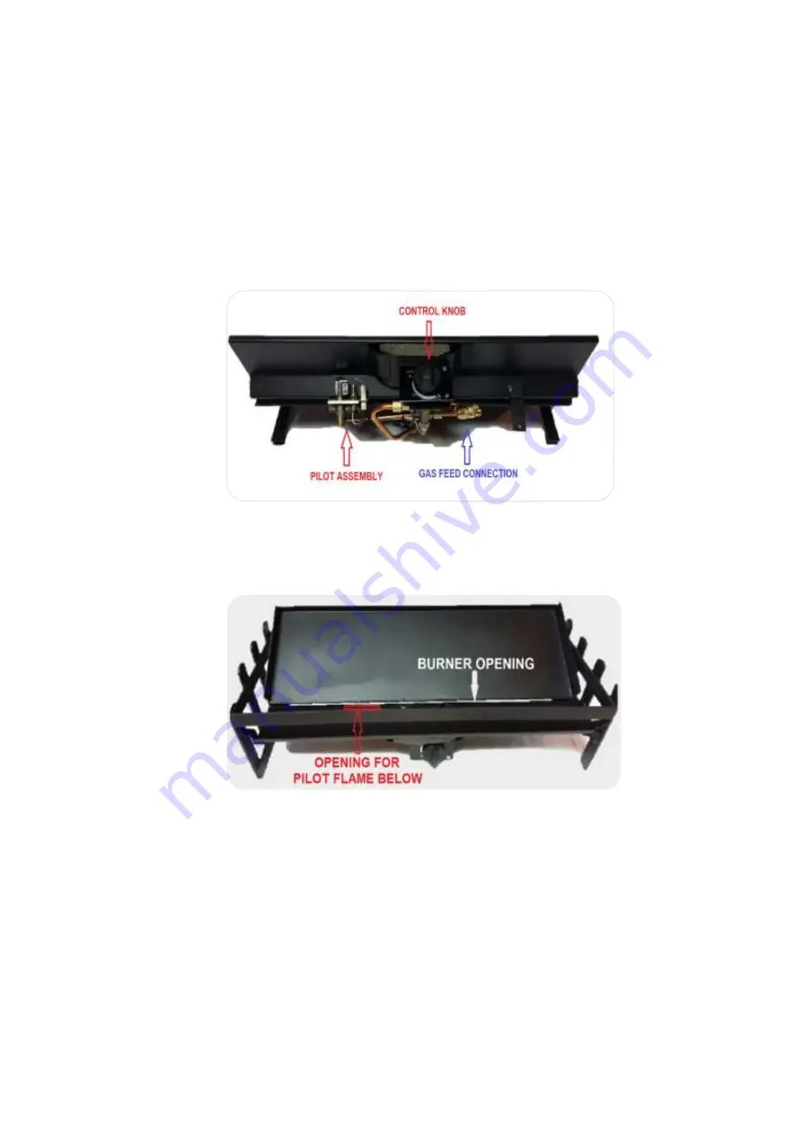
Place the gas grate on its back edge within the firebox body opening to expose the underside.
Remove the plastic valve cover by sliding it forward and run the gas pipe to the gas inlet port,
which for the gas burner is positioned on the right side of the control valve, when viewed from
the front. Connect the pipe with the 8mm compression nut / olive, making sure the connection
is tight, using a 16mm spanner. Do not strip it. Use of PTFE will invalidate the Warranty, as
small pieces can enter the pipe and damage the valve.
Illustration showing the underside of the gas grate:
Illustration showing the opening for the pilot flame as well as the slot where flames will rise from
the burner during grate activation.
Pressurise the gas supply line and test for leaks up to the valve, attaching a manometer or U-
gauge. The pressure should be 2.75 kPa in the case of an LPG installation and 2.0 kPa in the
case of an NG installation. Allow to stand for a minimum of 5 minutes. If the pressure drops,
then test joints for leaks with soapy water or electronic gas leak detector until the leak is found.
Rectify and then pressure test again.
Turn the gas grate back onto its base.
Fit the gas front and dummy ash-pan.
If installed in a Jetmaster Universal firebox, fit the gag, which is supplied with the gas grate, to
the Jetmaster damper friction bar, to prevent the damper from closing more than halfway.


