background image

P/N 960-000167R_Rev. 1 {EDP #214645} 

© 2013, Japan CashMachine Co., Limited

9

DT-300™ Series Download Tool Operator Integration Guide

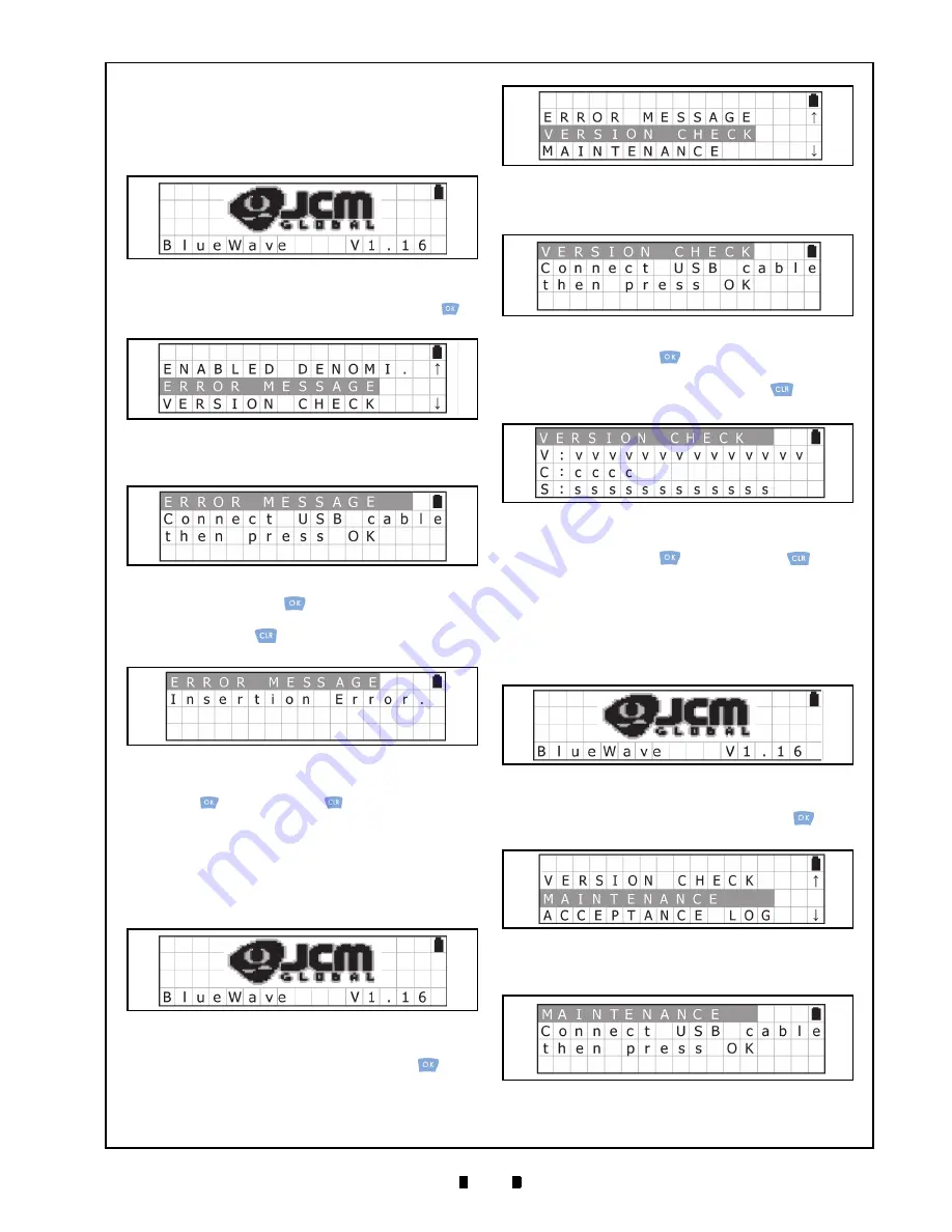
Error Message Function

To receive/display the error condition from the 

Validator, proceed as follows:

1.  Turn the DT-300™ Power Switch ON, and the 

SD Card check will begin (See Figure 27).

2.  Select the “

ERROR MESSAGE

” from the Func-

tion Selection Screen and press the 

OK

 Key

 to 

select it (See Figure 28).

3.  Make sure that the LCD displays the Standby 

Screen shown in Figure 29

4. Press 

the 

OK

 Key

 to display the Active Error 

Code Indication Screen shown in Figure 30. Press 

the 

CLR

 Key 

 to return to the previous Func-

tion Selection Screen.

5.  Confirm the Active Error Code. Press the 

OK


Key

 or the 

CLR

 Key

 to return to the previ-

ous Standby Screen.

Version Check Function

To obtain the Version, CRC and Serial Number 

from the Validator, proceed as follows:

1.  Turn the DT-300™ Power Switch ON, and the 

SD Card check will begin (See Figure 31).

2. Select 

VERSION CHECK

” from the Function 

Selection Screen and press the 

OK

 Key

 to 

select it (See Figure 32).

3.  Ensure that the LCD displays the Standby Screen 

shown in Figure 33. 

4. Press 

the 

OK

 Key

 to display the Version, 

CRC and Serial Number Indication Screen 

(See Figure 34). Press the 

CLR

 Key 

 to return 

to the previous Function Selection Screen.

5.  Confirm the Version, CRC and Serial Number. 

Press the 

OK

 Key

 or the 

CLR

 Key 

 to 

return to the previous Standby Screen.

Maintenance Function

To review/display the Maintenance Condition 

information of the Validator, proceed as follows:

1.  Turn the DT-300™ Power Switch ON, and the 

SD Card check will begin (See Figure 35).

2. Select 

MAINTENANCE

” from the Function 

Selection Screen and press the 

OK

 Key

 to 

select it (See Figure 36).

3.  Ensure that the LCD displays the Standby Screen 

(See Figure 37).

Figure 27 

SD Card Confirmation Screen 4

Figure 28 

Function Selection Screen 4

Figure 29 

Standby Screen 2

Figure 30 

Active Error Code Indication Screen

Figure 31 

SD Card Confirmation Screen 5

Figure 32 

Function Selection Screen 5

Figure 33 

Standby Screen 3

Figure 34 

Version, CRC & Serial Number Screen

Figure 35 

SD Card Confirmation Screen 6

Figure 36 

Function Selection Screen 6

Figure 37 

Standby Screen 4

Summary of Contents for BlueWaveDX

Page 1: ...Limited Support http www jcmglobal com en contact default aspx Web Site http www jcmglobal com Issue 4033 IGE 01 01 DT 300 Series Download Tool Operator Integration Guide Revision 1 April 1 2013 P N 9...

Page 2: ...ompanies Furthermore and are not always mentioned in each case throughout this publication International Compliance RoHS Directives CE Mark FCC Directives See below REVISION HISTORY Rev Date Reason fo...

Page 3: ...etting 6 Functions 6 Bootloader 6 MainApplication Normal Mode 6 Boot Mode 6 Authentication 6 USB Cable Connection 6 Operation Procedures MainApplication 6 Firmware Update Function 6 Statistics Functio...

Page 4: ...DT 300 Entire Unit Outside Dimensions 14 9 COMPATIBILITY 14 10 ERROR CODES 15 Bootloader Error Codes 15 MainApplication Error Codes 15 11 INTERNATIONAL COMPLIANCE 18 12 TECHNICAL CONTACT INFORMATION...

Page 5: ...en 7 Figure 15 Software Downloading Screen 7 Figure 16 Software Download Verifying Screen 7 Figure 17 Software Download Complete Screen 7 Figure 18 SD Card Confirmation Screen 2 7 Figure 19 Function S...

Page 6: ...42 Standby Screen 5 10 Figure 43 Acceptance Log Reading Screen 10 Figure 44 Log Read Complete Screen 10 Figure 45 SD Card Confirmation Screen 8 11 Figure 46 Function Selection Screen 8 11 Figure 47 L...

Page 7: ...ance Log 8 Table 7 Reading Denomination Table 8 Table 8 Log Storage Limit 10 Table 9 Acceptance Logs Available 10 Table 10 Performance and Battery Condition 12 Table 11 Battery Condition Indication 12...

Page 8: ...P N 960 000167R_Rev 1 EDP 214645 2013 Japan CashMachine Co Limited vi DT 300 Series Operator Integration Guide THIS PAGE INTENTIONALLY LEFT BLANK...

Page 9: ...ssignments Functions Unit Dimensions Compatibility Technical Contact Information In order to make operation of this device easier and make navigation within this manual simpler the following illustrat...

Page 10: ...features an LCD Display The Bootloader update and the MainApplication function selection are available by using the LCD Display The Acceptance Log Error Messages Version CRC Serial Number Maintenance...

Page 11: ...and repair should only be performed by a certified JCM Service Center or a professional technician Unauthorized repair use by inadequately trained personnel or use outside the manu facture s original...

Page 12: ...T LEFT Interface USB Host Single Channel USB 2 0 Full Speed SD Card SDHC acceptable USB is available for only JCM products access Display Monochrome LCD 122x32 dots with back light LED Light emitting...

Page 13: ...3 Save the Software Data Files xxxxxxxxx COM for each Model s Folder Refer to the Software Data File on page 13 of this Guide for more details SD CARD INSTALLATION INTO A DT 300 Perform the following...

Page 14: ...Validator to the DT 300 Device 1 Connect the USB Cable A Terminal to the DT 300 Unit s Connector A Port See Figure 9 a 2 Connect the USB Cable B or Mini B terminal to the Validator s USB Port See Fig...

Page 15: ...SB Cable See Figure 20 Once detected the connection between the Validator and the DT 300 will automatically begin to receive the Validator s Acceptance Log 4 The LCD Screen will display a Progress Bar...

Page 16: ...een shown in Figure 25 4 Press the OK Key to display the Denomina tion Table Screen See Figure 26 Press the CLR Key to return to the previous Function Selec tion Screen 5 Confirm that the current deno...

Page 17: ...election Screen and press the OK Key to select it See Figure 32 3 Ensure that the LCD displays the Standby Screen shown in Figure 33 4 Press the OK Key to display the Version CRC and Serial Number Ind...

Page 18: ...isplay a Progress Bar during the Acceptance Log reading process as shown in Figure 43 5 Once reading of the Acceptance Log is complete the LCD will display the Log Read Complete Screen shown in Figure...

Page 19: ...D Screen will display a Progress Bar during the Firmware updating pro cess as shown in Figure 49 4 Once the update is complete the LCD Screen will display the new Bootloader X XX Succeeded Message See...

Page 20: ...tion Key is pressed the DT 300 will again be ready to begin operation When the DT 300 Device enters Sleep Mode while downloading the Software or receiving the Acceptance Log the LCD Screen will displa...

Page 21: ...mmm_ssssssssssss_nnnn LOG mmm Model Name ssssssssssss Serial Number 12 digit decimal If the number was not read none nnnn Number 4 digit decimal e g UBA_0001 DAT iPRO1234 LOG NOTE The Backlight is li...

Page 22: ...OFF iVIZION System Type A Mini B VEGA Series Set DIP Switches 1 7 8 to ON and keep DIP Switches 2 through 6 OFF VEGA System Type A Mini B TBV 100 Series Set DIP Switches 1 6 7 8 to ON and keep DIP Swi...

Page 23: ...M Data File Access Error 11 E59 EEPROM Error EEPROM Data File Format Error 12 E60 EEPROM Error EEPROM Write Error 13 E61 SD Card Error Card Information File Authentication Error 14 E62 SD Card Error S...

Page 24: ...Error EEPROM Selected Language Write Error 39 E070 SD Card Error MMC Driver Initialize Error 40 E071 SD Card Error SD Card Power ON Error 41 E072 SD Card Error SD Card Power OFF Error 42 E073 SD Card...

Page 25: ...error 85 E420 Send Error Error Code Receive Request Error 86 E421 Receive Error Error Code Receive Response Error 87 E422 Mode Error SetMode 0x0A Command Send Error 88 E423 Mode Error SetMode 0xFF Com...

Page 26: ...mplies with Part 15 of FCC Rules Operation is subject to the following two conditions 1 this device may not cause interference and 2 this device must accept any interference received including interfe...

Page 27: ...190 837 7834 Unit B Third Avenue Denbigh West Business Park Bletchley Milton Keynes Buckinghamshire MK1 1DH UK E mail support jcm uk com ASIA OCEANIA JCM GOLD HK LTD Phone 852 2429 7187 Fax 852 2929...

Page 28: ...P N 960 000167R_Rev 1 EDP 214645 2013 Japan CashMachine Co Limited 2 0 DT 300 Series Download Tool Operator Integration Guide THIS PAGE INTENTIONALLY LEFT BLANK...

Page 29: ...tion steps required for 5 N Navigation within manual procedure for 1 P Pin Assignments 51 Pin D Sub Connector Table Listing of 13 Precautionary Symbols types of 3 Primary Features DT 300 Product Serie...

Page 30: ...P N 960 000167R_Rev 1 EDP 214645 2013 Japan CashMachine Co Limited 22 THIS PAGE INTENTIONALLY LEFT BLANK DT 300 SeriesOperator Integration Guide...

Page 31: ...P N 960 000167R_Rev 1 EDP 214645 2013 Japan CashMachine Co Limited DT 300 SeriesOperator Integration Guide...

Page 32: ...P N 960 000167R_Rev 1 EDP 214645 2013 Japan CashMachine Co Limited DT 300 SeriesOperator Integration Guide Issue 4033 IGE 01 01...

Reviews: