(N)ER2M050SD-SD
Trolley Control Box
Replacement Instructions
1 of 2
GENERAL USE
EDOC0498
Rev.01 04-02-2009
Purpose:
This document provides instructions for the replacement of the Trolley Control Box for
the (N)ER2M050SD-SD.
Required Tools: Size #2 Phillips screw driver, adjustable wrench (or pliers).
Parts: Replacement Trolley Control Box for MR050SD (not including cover and rubber gasket).
Est. Time: 15 min.
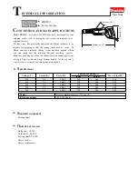
Refer to Fig. 1 and perform following steps.
1.
Remove Power: De-energize electric power to the unit, and lock & tag the power supply in the
de-energized position.
2.
Unplug the pendant from the Trolley Control Box (TCB). Leave the strain relief attached.
3.
Unplug the two connection cables.
4.
Remove cover (including screws) & rubber gasket from the TCB. Set aside for reuse.
5.
Disconnect & remove the power supply cable.
6.
Disconnect & remove motor cable (six wires) from the TCB - refer to diagram on inside of TCB
cover:
(a)
Disconnect X25 to detach the Brown wire.
(b)
Disconnect X26 to detach the Yellow wire.
(c)
Unplug X22 to disconnect the Black, Red, and Blue wires.
(d)
Remove the green wire from the ground screw.
7.
Remove the existing TCB and install the replacement TCB.
8.
Reconnect Motor Cable. Terminate the wires from 6(a) thru 6(d) above.
9.
Reconnect power supply cable: Red-L1, Blue-L2, Black-L3, Green-ground screw.
10.
Install TCB cover & rubber gasket (reuse the screws, cover, and gasket from 4 above).
11.
Plug in the pendant. Apply power & confirm proper operation.
12.
Return the removed TCB. Mark “RGA# R6822” on the shipping box. Mail to the following
address using
UPS account 182557
:
Attn: Product Support
Harrington Hoists, Inc
401 West End Avenue
Manheim, Pa 17545
Question and comments, call Product Support at 1-800-233-3010.