


Page 38
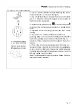
7.3.7 Use of foot pedal controller
1. The foot remote controller consists internally of a switch
and potentiometer, as shown in the figure.
2. Use a dedicated cable to connect the remote controller to
pins 1, 2, 3, 8 and 9 of the torch trig
ger’s aviation socket on
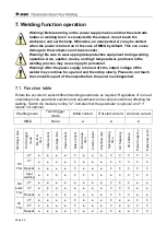
the front panel of the welder.
3. Under no load, press the key
to turn the indicator
on. At this time, the foot pedal controller is in remote control
mode.
4. Adjust the maximum welding current on the panel to start
welding.
5. Step on the foot remote controller to start the arc,
generally using the non-contact arc starting mode. After it is
started, the welding current will be controlled by the foot
remote controller, using the maximum output of the current
setting.
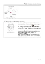
6. Pin 2 is the common potentiometer port. When the foot
remote controller current is at the minimum, the resistance
of pins 1 and 2 is 10kΩ, and of pins 2 and 3 is 0Ω; when the
current is at the maximum, the resistance of pins 1 and 2 is
0Ω, and of pins 2 and 3 is 10kΩ.
Note: The foot pedal controller is optional. Select it before
placing an order if required.
9-pin aviation socket
of foot pedal controller
7-pin aviation socket
of foot pedal controller


