
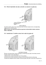
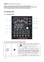
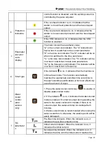


Page 31
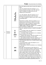
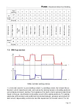
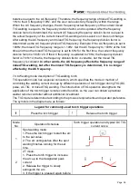
start time is correlated with the arc starting current
– the greater the current, the shorter the
arc start time.
2. I
f
(plus arc force current) = I
Δf
(arc force current) + I
a
(welding current). Use the electrode
diameter, set current and process requirements to determine the arc force current. High arc
force settings lead to faster metal transfer and non-sticking electrode but with some spatter.
Lower arc force settings provide a smooth arc with less spatter and good weld seam
formation, but sometimes the arc is soft or the welding electrode can stick. The arc force
should be increased especially when welding thick electrodes under small current. Generally,
the arc force is should be set to 20-40A.
3. After the short-circuit time exceeds Tp, it enters anti-sticking electrode current, which is
smaller, until the electrode is separated from the workpiece.
4. U
0
is open circuit voltage and Uw is working voltage. When not performing MMA welding,
the welder outputs the open circuit voltage U
0
or the VRD voltage.
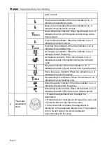
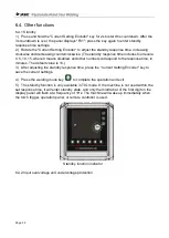
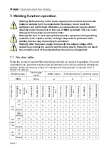
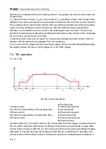
7.3. TIG operation
7.3.1 DC TIG
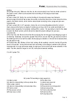
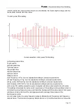
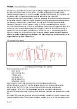
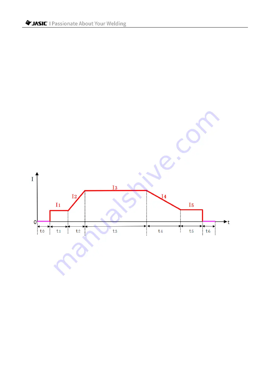
DC TIG current waveform
t0-Pre-flow time
I1-Initial current
t1-Initial current period
I2-Current corresponding to the up-slope time
t2-Up-slope time
I3-Peak current
t3-Peak current period
I4-Current corresponding to down-slope time
t4-Down-slope time
I5-Finish current
t5-Finish current period
t6-Post-flow time
● Initial current (I1): The initial current is the current after the torch trigger is pressed to start
the arc, which should be determined according to the process requirements. A large initial
current makes it easy to start the arc, but it should not be too large when welding thin plates,
otherwise, it may burn through the workpiece. After the arc is started in 4T operation, the
current remains at the initial current to achieve the purpose of preheating the workpiece or


