background image

27


NAVIGATING THE ‘LCD’ CONTROL PANEL


System Setting 

-

 Selection and Adjusting


Restored Parameter Settings


The factory parameter settings for the EM

-

200CT machine are as shown in the table below.


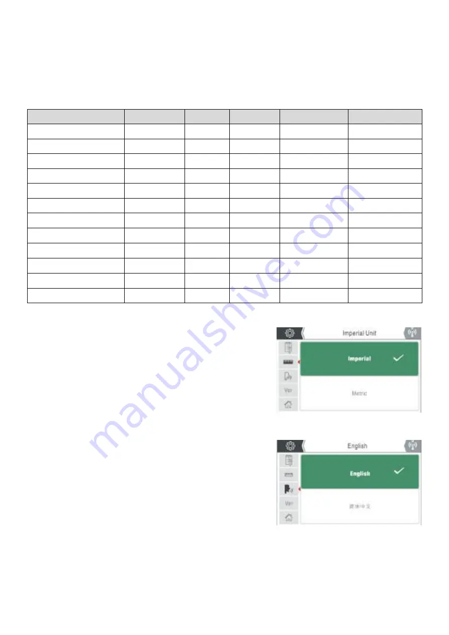
Unit System Setting


On entering this option, there are two unit system options: 
‘Metric System’ and ‘Imperial System’. Parameters related to      
the unit system conversion with the EVO MIG range include:


• 

Wire feed speed: Metric: m/min, Imperial: inches/min. 


• 

Welding wire diameter: Metric: mm, Imperial: inches.


• 

Plate thickness: Metric: mm, Imperial: inches.


Language Selection


To enter the system information screen, rotate the control dial     
to select the language icon (as shown right) and press control         
dial button to access the language choice screen.


Rotating the control dial clockwise or anticlockwise will scroll      
you through the language choice options. 


Once set on your required language choice, pressing the control 
dial button will save your chosen setting. 


Press the return button to go back to the previous screen.


Parameter


Unit


MMA


Lift  TIG


Standard MIG


Synergic MIG


Pre

-

flow time


Seconds


0.5


0.5


0.5


Peak current


Amps


100


100


100


Down

-

slope time


Amps


0.5


0.5


0.5


Post

-

flow time


Seconds


2


2


2


Welding current


Amps


100


Burn Back Voltage


Volts


13


13


Hot start current


Amps


30


Arc

-

force current


Amps


30


Standby Time


Seconds


10


10


10


10


Voltage Protection


Off


Off


Off


Off


Slow Wire Feed Speed


3


3


3


3


Remote Control Mode


Wireless


Wireless


Wireless


Wireless


Summary of Contents for EVO 2.0

Page 1: ...1...

Page 2: ...rect information should you require assistance or spare parts Date purchased ________________________________________ From where ________________________________________ Serial number ________________...

Page 3: ...ronment 7 Protection from moving parts 7 Magnetic fields 7 Compressed gas cylinders and regulators 7 RF declaration 8 LF declaration 8 Materials and their disposal 9 Description of Symbols 10 Descript...

Page 4: ...g should be regularly checked for damage and overheating Never use worn damaged under sized or poorly jointed cables Insulate yourself from work and earth using dry insulating mats or covers big enoug...

Page 5: ...cutting is taking place Wear suitable protective flame resistant clothing gloves and footwear Ensure adequate extraction and ventilation is in place prior to welding and cutting to protect users and...

Page 6: ...ding fume Ensure the welding zone is well ventilated and provision should be made for suitable local fume extraction system to be in place If ventilation is poor wear an approved airfed welding helmet...

Page 7: ...ated by high currents may affect the operation of pacemakers or electronically controlled medical equipment Wearers of vital electronic equipment should consult their physician before beginning any ar...

Page 8: ...permanent damage to your hearing Noise from cutting and welding equipment can damage hearing Always protect your ears from noise and wear approved and appropriate ear protection if noise levels are hi...

Page 9: ...dangerous to the operator Do not dispose of the equipment with normal waste The European Directive 2012 19 EU on Waste Electrical and Electronic Equipment states that electrical equipment that has rea...

Page 10: ...fective input current X Duty cycle The ratio of given duration time the full cycle time U0 No load voltage Open circuit voltage of secondary winding U2 Load voltage H Insulation class Do not dispose o...

Page 11: ...carbon steel Self shielded welding of carbon steel 100 argon shielding of aluminum magnesium alloy Mixed gas welding 98 argon 2 CO2 of stainless steel Welding type selection welding base metal and gas...

Page 12: ...CT 15 Home Button Pressing the home button will take you directly back to the home screen as shown in the display area image on page 13 16 The parameter control dial is also a control button which whe...

Page 13: ...f the machine increases or decreases parameter values including welding current and when these parameters are adjusted the values are shown in the display screen Parameter adjustment knob A Parameter...

Page 14: ...entral control dial to select the following option of MIG Synergic MIG Standard MMA Lift TIG Settings and User manual then press the central control dial button to select the required welding mode Tex...

Page 15: ...or anti clockwise allows the user to navigate around the screen options adjust welding current or the various welding parameters that are available in all welding modes and user setting options 3 Hom...

Page 16: ...settings When in any of the welding modes P function settings is a secondary menu where additional functions can be adjusted and set For example Material thickness wire size Pre post gas trigger mode...

Page 17: ...t parameters as per example shown on page 15 for Synergic MIG from left to right parameters are set as follows Welding wire size 2T trigger mode welding inductance value pre gas time post gas time and...

Page 18: ...een 0 2 seconds for MIG and 0 5 seconds for TIG Post Gas Time Post flow time icon indicates the gas post flow time which can be adjusted between 0 5 seconds for MIG and 0 10 seconds for TIG Material T...

Page 19: ...re more parameters or options available but are located off screen continuing to rotate the central control dial will allow access to these additional parameter or options as noted in image B on page...

Page 20: ...TIG mode the current can only be adjusted by the master encoder 2 Adjustment of other welding parameters Except for current and voltage all other parameters can only be adjusted in Parameter Settings...

Page 21: ...ollowing steps If the user wants to adjust the operating mode in Synergic MIG rotate the central encoder to select and enter Parameter Settings P screen then rotate the encoder to select highlight and...

Page 22: ...u to scroll through system icon options User Background Settings As per previous page to access and adjust user background settings from the home screen navigate to the background settings icon which...

Page 23: ...n MIG and TIG mode if activated If the machine is not used within the preset period of time 5 minutes for example the machine will then enter a standby state where the unit powers down and the screen...

Page 24: ...vely Remote Control Selection The EVO machine range of machines allow the user to use either wired or wireless technology for remote control purposes that offers the user to use wired or wireless hand...

Page 25: ...ess device This is confirmed by the screen showing Pairing please wait Ensure that your remote device is in pairing mode see remote control instructions supplied with your device Once wireless pairing...

Page 26: ...uired option of either Sure or Cancel as shown below 3 Once you have pressed the control dial on the highlighted green sure tab a new pop up green box will be displayed indicating Waiting for factory...

Page 27: ...ct the language icon as shown right and press control dial button to access the language choice screen Rotating the control dial clockwise or anticlockwise will scroll you through the language choice...

Page 28: ...ual screen you can rotate the control dial to select the section tabs on the left of the screen which are Operation Components Spare Parts Maintenance When you select for example select and enter the...

Page 29: ...rror code is indicated along with the corresponding error description appears on the LCD display as the example right shows As long as an error code is shown welding operation is generally not possibl...

Page 30: ...dial and for example pressing the Load option recall the saved welding parameters and load said program Pressing the back button will take you to the recalled welding screen where you can then commen...

Page 31: ...s detailed below Work return lead to B and the torch trailing lead to A Ensure that a suitable shielding gas supply is connected Switch the power switch on the back panel to ON the machine is started...

Page 32: ...mode icon is highlighted green then press the central dial button to select trigger mode This icon shown in the above screen image represents 2T torch trigger mode when this trigger option is selected...

Page 33: ...select a saved welding job or save a welding job to and from the Memory function screen Once in the memory page you will note there are 4 memory slots to Select M1 M2 M3 and M4 and if a welding job w...

Page 34: ...ttings Welding voltage is controlled and adjusted via the right control dial C When welding voltage is adjusted arc length also changes proportionally with it Rotating dial C clockwise will increase t...

Page 35: ...ng rotate the central control dial until trigger mode icon is highlighted green then press the central dial button to select trigger mode This icon shown in the above screen image represents 2T torch...

Page 36: ...you to the specific memory slot option page where you have three options of Save Load or Delete Selecting your desired option is carried out by rotating the control dial and for example pressing the...

Page 37: ...t up the fan may start to rotate as the welding machine powers up and the control panel will also light up to indicate that the machine is ready to use as shown below PLEASE NOTE Caution when in MMA m...

Page 38: ...ch as hot start and arc force and these can be adjusted via the parameter P mode By pressing and then rotating the central control dial you can scroll to the parameter function to set back end MMA par...

Page 39: ...ckwise Insert the dinse plug on the work return cable into the socket on the front panel of the machine and rotate clockwise to tighten Attach the work clamp to the work piece Connect the supply gas h...

Page 40: ...s Lift TIG pre gas selection and adjusting To select pre flow gas time setting rotate the central control dial until preflow is highlighted green then press the central dial button to adjust pre flow...

Page 41: ..._________ _____________________________________ _____________________________________ _____________________________________ _____________________________________ _____________________________________...

Page 42: ...42...

Reviews: