SETUP AND ADJUSTMENT
2-18
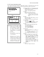
2.2.5.6 Tx power adjustment per channel
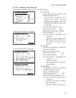
Tx power for each user channel is applied from the Tx power for each band of the factory default
setting. After installation check the Tx power for each user channel and, adjust it if necessary.
Furthermore, the user channels information are saved as below.
Controller
: Group name, Channel number, Communication mode, Frequency
PA UNIT
: Channel number, Frequency, Tx power
z
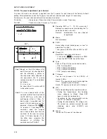
Pressing ENT on "1. TX CH power adj."
displays a popup screen for adjusting the Tx
power as shown on the left.
Remark: Inaccessible if no user channel
is registered.
z
Mode
Not selectable.
z
PWR
Select either High (rated power) or Low* to
adjust the Tx power.
* Low power is 50W for HF and 33W for MF.
z
Group-CH
Select the user channels to be set.
* if not tuned,
TUNE
is displayed at PWR.
Press the ANT TUNE key at that time.
z
Type
Select a TX type for the communication mode.
TEL: Test tone/MIC
DSC: 1615Hz/1785Hz/Dot
TLX: 1615Hz/1785Hz/Dot
CW: (setup unnecessary)
z
TX
power
Can be set between 0.5 to 200.0% of
typical (100%).
Note1. The upper and lower limits might be
refused by the PA limiter.
Note2. TX power can be set at 0.5% steps.
z
[TX]
Starts transmitting by the conditions above.
During the transmission, this handling
menu changes to [Stop]. Press ENT
again to stop the transmission.
According to the communication mode,
the PTT or CWKEY is available.
During the transmission, PA voltage (Vc),
PA current (lc), antenna current (la), and
standing wave ratio (SWR-P) are
displayed.
z
[Save]
Saves the TX power of the channel.
ENT
↓
Note1:
Based on the PA voltage (Vc)
and PA current (lc) checked here
and the efficiency
η
written in
the inspection data attached to
the equipment, the Tx power
(antenna power) P is calculated
as follows.
P = Vc x lc x
η
So check that P is within ±20%
to the rated power.
Note2:
If a user channel data of the
controller differs from the data of
the PA UNIT, e.g. in the case of
exchanging either of them, Tx
band power is applied and Tx
power of that channel cannot be
adjusted. (Displays PWR:
Band
.)
To resume it, if exchanged the
controller, send the original
user channel table from the old
controller to the new one using
menu 7.3.5 data transfer. Or in
the other case, reregister the
channel(s) or initialize the
controller and/or PA UNIT.
Summary of Contents for JSS-2150
Page 2: ... ...
Page 14: ......
Page 43: ...CONFIGURATION AND SPECIFICATIONS 1 29 ...
Page 44: ...CONFIGURATION AND SPECIFICATIONS 1 30 ...
Page 45: ...CONFIGURATION AND SPECIFICATIONS 1 31 ...
Page 52: ...CONFIGURATION AND SPECIFICATIONS 1 38 2 Antenna tuner NFC 2150 wiring diagram ...
Page 67: ...SETUP AND ADJUSTMENT 2 7 2 2 3 Menu tree ...
Page 68: ...SETUP AND ADJUSTMENT 2 8 ...
Page 84: ...SETUP AND ADJUSTMENT 2 24 ...
Page 108: ...Maintenance 4 10 ...
Page 128: ...Maintenance 4 30 ...
Page 132: ...APPENDIX 5 4 5 1 4 CMJ 2250 WKR MODEM UNIT DMC TRX DIODE SWITCH DIODE SWITCH ...
Page 134: ...APPENDIX 5 6 5 1 6 NDZ 227 DATA TERMINAL ...
Page 137: ...APPENDIX 5 9 ...
Page 138: ...APPENDIX 5 10 ...
Page 139: ...APPENDIX 5 11 ...
Page 140: ...APPENDIX 5 12 ...
Page 141: ...APPENDIX 5 13 ...
Page 142: ...APPENDIX 5 14 ...
Page 143: ...APPENDIX 5 15 ...
Page 144: ...APPENDIX 5 16 ...
Page 145: ...APPENDIX 5 17 ...
Page 146: ...APPENDIX 5 18 ...
Page 147: ...APPENDIX 5 19 ...
Page 148: ...APPENDIX 5 20 ...
Page 149: ...APPENDIX 5 21 ...
Page 150: ...APPENDIX 5 22 ...
Page 151: ...APPENDIX 5 23 ...
Page 152: ...APPENDIX 5 24 ...
Page 153: ...APPENDIX 5 25 ...
Page 154: ...APPENDIX 5 26 ...
Page 155: ...APPENDIX 5 27 ...
Page 156: ...APPENDIX 5 28 ...
Page 159: ......


