SETUP AND ADJUSTMENT
2-2
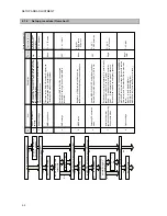
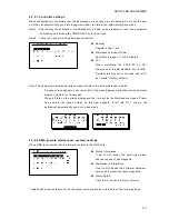
2.1.2 Setup procedure (flowchart)
Is it
used a
s G
M
DSS?
Set F1.1.1 ID setup
Are two c
ontroll
ers
con
necte
d?
-
S
et RS-485 termin
ator
-
S
et F
1
.3.1 Add
ress
No
Ye
s
No
Ye
s
No
Yes
Is
NBD-21
50 AC/DC power uni
t bein
g use
d?
Ye
s
No
Is DMC or si
mple
AME
conne
cted?
No
Yes
Is Inma
rsat C run
ning
paral
lel
duri
ng DC
operati
on?
No.
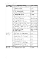
Item
Descr
iption
Defau
lt
Operati
on (Menu)
3
MMSI regi
stration
This
is
the s
hip's
9 digi
t ID numbe
r. Regi
ster the
numb
er a
ssi
gned b
y the a
dmini
strati
on.
* E
ntering a
ll 0
s erase
s the regi
stratio
n.
None
F
1.1.
1 ID setup
4
DMC settings
Se
t to ON i
f DMC (NCH-321A) is con
necte
d.
Se
t the DMC set
ting to
Exp
if si
mpl
e AME i
s
connec
ted.
OF
F
F
1.2.
1.1 DMC
5
Detect
ing DC operati
on
mode
Use
the NBD-2150 A
C
/D
C po
wer s
uppl
y and
set
“Detect DC op
erati
on mod
e vi
a DC_OP
E”
to ON.
OF
F
F
1.2.
4.1
AC/DC detec
tion
6
Inmarsat-C parall
el
operatio
n setti
ngs
during
DC operation
mode
Se
t whether or not to run Inmars
at-C i
n parall
el whi
le
ope
rati
ng the J
S
S
-215
0 on DC power.
Si
ngl
e:
Disa
ble pa
ral
lel
Inmarsat-C operati
on.
Dual
:
E
nabl
e parall
el
Inmarsat-C operation
*S
et dual
if the
shi
p has
an emergenc
y ge
nerator.
Sin
gle
F
1.2.
4.2
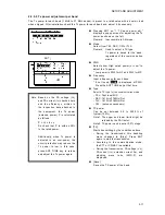
BAT
T u
se s
et
Is a prin
ter c
onnec
ted?
Ye
s
Set 7
.6 Opti
on
No
7
Opti
on setting
s
To us
e a printer, s
et 7.6.1 Conn
ecti
on to S
eri
alP
R
N o
r
NKG
-8
00. Set th
e other se
ttings
(Dat
a out, Ba
udra
te,
Flow c
ontrol, an
d Print di
re
cti
on) l
ik
e the ex
ampl
es
bel
ow.
NKG
-9
1:
A
uto/4
.8k/Hard/Inv
ert
DPU-414:
Auto/4
.8k/Hard/Upright
NKG
-8
00:
Auto (Ot
her th
an Data out
is
fixe
d.)
None/
CMD
7.6 Op
tion
Se
tup flo
w
chart (1
/2)
8
Is
NDZ-227 da
ta terminal
conn
ected
?
Se
t N
B
DP setup
Ye
s
No
NBDP setup
Regi
ster 4 or 5 di
git s
elc
al n
umber and the
ans
werb
ack
code
ass
igne
d by th
e admi
nis
trati
on
None
Sys
tem –
N
B
DP se
tup
* DTE
menu
1
RS-485 termina
tor
setti
ngs
If two c
ontroll
ers
are con
necte
d, the termin
al on t
he
one
nearest the
tran
sce
iv
er mu
st be tu
rned
off for RS-
485
commun
ica
tions
.
ON
Set TB101
ins
ide
back
panel
of
controll
er
2
Addres
s s
etting
s
If two c
ontroll
ers
are con
necte
d, a di
fferen
t address
mus
t be s
et for each
one.
1
F1.3.
1 Addres
s
Summary of Contents for JSS-2150
Page 2: ... ...
Page 14: ......
Page 43: ...CONFIGURATION AND SPECIFICATIONS 1 29 ...
Page 44: ...CONFIGURATION AND SPECIFICATIONS 1 30 ...
Page 45: ...CONFIGURATION AND SPECIFICATIONS 1 31 ...
Page 52: ...CONFIGURATION AND SPECIFICATIONS 1 38 2 Antenna tuner NFC 2150 wiring diagram ...
Page 67: ...SETUP AND ADJUSTMENT 2 7 2 2 3 Menu tree ...
Page 68: ...SETUP AND ADJUSTMENT 2 8 ...
Page 84: ...SETUP AND ADJUSTMENT 2 24 ...
Page 108: ...Maintenance 4 10 ...
Page 128: ...Maintenance 4 30 ...
Page 132: ...APPENDIX 5 4 5 1 4 CMJ 2250 WKR MODEM UNIT DMC TRX DIODE SWITCH DIODE SWITCH ...
Page 134: ...APPENDIX 5 6 5 1 6 NDZ 227 DATA TERMINAL ...
Page 137: ...APPENDIX 5 9 ...
Page 138: ...APPENDIX 5 10 ...
Page 139: ...APPENDIX 5 11 ...
Page 140: ...APPENDIX 5 12 ...
Page 141: ...APPENDIX 5 13 ...
Page 142: ...APPENDIX 5 14 ...
Page 143: ...APPENDIX 5 15 ...
Page 144: ...APPENDIX 5 16 ...
Page 145: ...APPENDIX 5 17 ...
Page 146: ...APPENDIX 5 18 ...
Page 147: ...APPENDIX 5 19 ...
Page 148: ...APPENDIX 5 20 ...
Page 149: ...APPENDIX 5 21 ...
Page 150: ...APPENDIX 5 22 ...
Page 151: ...APPENDIX 5 23 ...
Page 152: ...APPENDIX 5 24 ...
Page 153: ...APPENDIX 5 25 ...
Page 154: ...APPENDIX 5 26 ...
Page 155: ...APPENDIX 5 27 ...
Page 156: ...APPENDIX 5 28 ...
Page 159: ......


