background image

CONFIGURATION AND SPECIFICATIONS   

1-22 

(11)


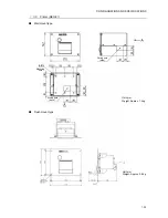
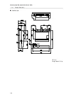
Printer (NKG-800)   


Desktop type 


Unit: mm 
Weight: Approx. 3.7 kg 

Summary of Contents for JSS-2150

Page 1: ...SERVICE SERVICE MANUAL MANUAL 150W MF HF RADIO EQUIPMENT 150W MF HF RADIO EQUIPMENT JSS 2150 JSS 2150 ...

Page 2: ... ...

Page 3: ...t hand in your pocket in order not to use both hands simultaneously are also very good methods of shock prevention Quite often an injury occurs by secondary factors therefore it is necessary to choose a sturdy and level working surface If someone is electrocuted it is necessary to thoroughly disinfect the affected area and seek medical attention as soon as possible When you find an electrocution v...

Page 4: ...osen any constrictive clothing a tie or belt 5 a Check the victim s pulse b Check for a heartbeat by pressing your ear against the victim s chest c Check if the victim is breathing by putting the back of your hand or face near the victim s face d Check the pupils of the eyes 6 Open the victim s mouth and remove any artificial teeth cigarette or chewing gum Leave the mouth opened and flatten the to...

Page 5: ...ostrils then blow air in while covering the mouth and the other nostril 6 Occasionally when the victim comes back to consciousness they immediately try to stand up Prevent this and keep them in a laying position Give them something warm to drink and be sure that they rest do not give them any alcohol Administering artificial respiration by raising the head 1 Raise the back of head then place one h...

Page 6: ...id when alone Perform the heart massage about 15 times then blow in twice Repeat this routine If administering first aid with two people One person performs the heart massage 5 times and the other person blows air in once Repeat this routine Heart massage and mouth to mouth resuscitation used together 3 Constantly check the pupils and the pulse if the pupils become normal and the pulse steadies ke...

Page 7: ...ol specifies the content of the caution more accurately This example warns of possible electrical shock The symbol indicates that performing an action is prohibited The illustration inside the symbol specifies the contents of the prohibited operation in this example disassembly is prohibited The z symbol indicates operations that must be performed The illustration inside the z symbol specifies obl...

Page 8: ...orten transmitting time When repairing a RoHS compatible unit use RoHS compatible parts and lead free solder and also RoHS compatible wiring materials If a false distress alert is transmitted accidentally follow the instructions below 1 Press the CANCEL key on the controller when appropriate follow the commands on screen and terminate the transmission of the distress call 2 Report the false distre...

Page 9: ...d from icing In the field maintenance mode all DSC functions including distress alert and NBDP functions cannot be used So when setup is complete always restart by powering off and on using breakers or place the system in sleep mode If the equipment is left without operating in this mode the maintenance mode off timer automatically put the system into sleep mode Use F2 3 3 Calibration menu only wh...

Page 10: ...1 3 Specifications 1 6 1 3 1 JSS 2150 MF HF Radio Equipment 1 6 1 3 2 Options 1 10 1 3 3 Peripheral interfaces 1 12 1 3 4 External dimensions 1 16 1 4 Interconnection diagram 1 25 1 4 1 General configuration 1 25 1 4 2 Overall configuration 1 26 1 5 Exploded views and wiring diagrams 1 28 1 5 1 NTD 2150 MF HF Transceiver 1 28 1 5 2 NCM 2150 MF HF Controller 1 34 1 5 3 NFC 2150 Antenna tuner 1 37 1...

Page 11: ...nsmission conditions 2 16 2 2 5 5 Tx power adjustment per band 2 17 2 2 5 6 Tx power adjustment per channel 2 18 2 2 5 7 DSC NBDP AF measurement 2 19 2 2 5 8 Calibration for meters and radio frequency 2 19 2 2 5 9 Setting the receiving conditions 2 20 2 2 5 10 Initializing stored information 2 21 2 2 5 11 Upgrading the software 2 23 2 2 5 12 Checking the DISTRESS key operation history 2 23 3 OPERA...

Page 12: ... 4 Countermeasures for other malfunctions 3 14 4 MAINTENANCE 4 1 4 1 Periodic inspections 4 1 4 1 1 Checklist 4 1 4 1 2 Measuring DSC NBDP AF 4 2 4 1 3 Measuring the test tone 4 2 4 2 Unit replacement 4 3 4 2 1 Service parts list 4 3 4 2 2 Stored information list 4 10 4 3 Upgrading the software 4 13 4 3 1 Normal upgrade 4 14 4 3 2 Upgrading at the transceiver 4 19 4 4 Maintenance mode of the data ...

Page 13: ...ENT PROCEDURE for the CMV 3775 AF CONTROL UNIT 5 15 REPLACEMENT PROCEDURE for the CDJ 3775 CONTROL UNIT 5 17 REPLACEMENT PROCEDURE for the CCK 3775 MAIN PANEL UNIT 5 19 REPLACEMENT PROCEDURE for the CCK 3776 SUB PANEL UNIT 5 20 REPLACEMENT PROCEDURE for the CFG 2150 MATCHING UNIT 5 21 REPLACEMENT PROCEDURE for cooling fans 3108NL 05W B50 L09 5 23 REPLACEMENT PROCEDURE for the CCN 3227 COLOR LCD UN...

Page 14: ......

Page 15: ...Y 6 MF HF controller NCM 2150 One additional controller available 6 1 Controller cable 7ZCJD0343 5m 6 2 Handset NQW 261 Waterproof type IP66 equivalent 6 3 Flush mounting bracket MPBC42957 6 4 Mounting bracket MPBX44354 6 5 Connection box NQD 2250 For extension and expansion of the controller 7 Printer NKG 800 7 1 Printer connection cable 6ZCSC00407 7 2 Printer power cable 6JNKD00100B 7 3 Printer ...

Page 16: ...150 One additional controller available 6 1 Controller cable 7ZCJD0343 5m 6 2 Handset NQW 261 Waterproof type IP66 equivalent 6 3 Flush mounting bracket MPBC42957 6 4 Mounting bracket MPBX44354 6 5 Connection box NQD 2250 For extension and expansion of the controller 7 Data terminal NDZ 227 7 1 DTE cable 7ZCJD0388 7 2 DTE power cable 7ZCJD0419 7 3 Keyboard NDF 369 For expansion of the controller 7...

Page 17: ...ver Expansion Controller The radiotelephone can also be used when connected to remote maintenance system equipment NFC 2150 Antenna Tuner NBD 2150 AC DC Power Supply NBB 724 Battery Charger NCM 2150 MF HF Controller NQW 261 Handset NKG 800 Printer NDZ 227 Data terminal NDF 369 Keyboard DSC NBDP model only ...

Page 18: ... M P 7 Tx antenna Rx WKR antenna TTYCS 4 DPYC 2 5 7ZCJD 0343 5m NQD 2250 Connection box NFC 2150 Antenna tuner TX ANT TTYCYS 4 Lead wire TH 7 1 6 NQD 2253 Junction box NCM 2150 MF HF Controller NQW 261 Handset JQD 69C Joint box 100V 220V AC 50 60Hz 1φ TTYCS 1 NBB 724 Battery charger 7ZCJD0347 7ZCJD0349 7ZCJD0348 NCH 321A DMC RG 10 UY M P 7 M P 5 M A JJ NQD 2250 Connection box Expansion controller ...

Page 19: ... 4 DPYC 2 5 7ZCJD 0343 5m NQD 2250 Connection box NFC 2150 Antenna tuner TX ANT TTYCYS 4 Lead wire TH 7 1 6 NQD 2253 Junction box NCM 2150 MF HF Controller NQW 261 Handset JQD 69C Joint box 100V 220V AC 50 60Hz 1φ TTYCS 1 NBB 724 Battery charger 7ZCJD0347 7ZCJD0349 7ZCJD0348 NCH 321A DMC RG 10 UY M P 7 M P 5 M A JJ NDZ 227 Data terminal NDF 369 Keyboard NKG 800 Printer NQD 2250 Connection box Expa...

Page 20: ...teria IMO A 806 19 A 694 17 MSC68 68 MSC Circ 862 IEC 60945 Ed 4 2002 08 Power supply voltage 24 VDC 21 6 VDC to 31 2 VDC Current consumption 150W transmission Maximum 30 A Reception Maximum 5 A Operating temperature range 15 C 55 C parts exposed to condensation 25 C 55 C Storage temperature range 15 C 55 C parts exposed to condensation 25 C 70 C Humidity resistance No abnormality after standing 4...

Page 21: ... or less 1605 0 to 27500 0 kHz F1B 0 7 uV or less 1605 0 to 27500 0 kHz A1A 1 4 uV or less 1605 0 to 27500 0 kHz Pass band Adjacent signal selectivity J3E 2 4 3 0 kHz 6 dB bandwidth within 2 1 kHz 66 dB bandwidth F1B 270 300Hz 6 dB bandwidth within 550 Hz 60 dB bandwidth Spurious response J3E 60 dB or more F1B Symbol error rate of 1 or better at a wanted signal level of 10 uV and an unwanted signa...

Page 22: ...odulation rate Within 100 baud 30x10 6 Modulation method FSK sub carrier 1700 Hz Mark frequency Y Transmission Within 1615 Hz 0 5 Hz Reception permissible value Within 1615 Hz 20 Hz Space frequency B Transmission Within 1785 Hz 0 5 Hz Reception permissible value Within 1785 Hz 20 Hz DSC protocol ITU R recommendation M 493 11 Class A and B DSC operation standards ITU R recommendation M 541 9 M 821 ...

Page 23: ... PS 2 Printer interface Centronics compliant LCD display 10 4 inch TFT color 640x480 dots CCFL backlight Standard brightness 450cd m 2 Viewing angle 160 ゚ 140 ゚ Contrast 600 1 Keyboard Communication interface Serial two wire interactive transmission Connector Mini DIN 5Pin Durability 20 000 000 times Printer NKG 800 Printing system Serial impact dot matrix Communication interface Centronics compli...

Page 24: ...n 7 m s2 fixed No abnormality after testing resonance points or at 30 Hz for more than 2 hours Continuous operation No abnormality after operating continuously for 8 hours 2 Battery charger NBB 724 Source voltage 90 VAC 132 VAC or 180 VAC to 264 VAC 50 60 Hz Current consumption Charging 15 A or less 100 VAC input 8 A or less 220 VAC input Discharging 0 5 A or less at 24 VDC operation Charging curr...

Page 25: ...um print speed 20 mm sec or more Roll paper width 58 mm Power supply voltage 6 5 VDC 5 VDC to 8 7 VDC Current consumption Maximum 2 A 4 Printer DPU 414 Printing system Thermal serial dot Communication interface RS 232C 4 8k 9 6k 38 4kbps Data control HW busy Data buffer About 28kbyte Maximum print speed 52 5cps Roll paper width 112mm Power voltage 6 5VDC Current consumption Maximum 2A ...

Page 26: ...t Non parity Input sentence NMEA0183 V1 5 GGA GLL RMC V2 0 GGA GLL RMC ZDA V2 3 GGA GLL RMC GNS ZDA Talker GP or other Data type Ship position time information GGA GNS GLL RMC Date information ZDA RMC Equipment time information ZDA GGA GNS GLL RMC 1 1 Electrical description Load requirements Current consumption 2mA at 2V or less Maximum input voltage 15V or more Recommended operating current 2mA o...

Page 27: ...on Units of antenna altitude m Antenna altitude above below mean sea level geoid Horizontal dilution of precision Number of satellites in use 00 12 may be different from the number in view GPS quality indicator Longitude E W Latitude N S UTC of position 1 2 2 GLL Geographic position Latitude longitude GLL llll ll a yyyyy yy a hhmmss ss A a hh CR LF Mode indicator A Autonomous D Differential E Esti...

Page 28: ...g UTC of position fix 1 2 4 GNS GNSS fix data GNS hhmmss ss llll ll a yyyyy yy a c c xx x x x x x x x x x x hh CR LF Differential reference station ID Age of differential data Geoidal separation m Antenna altitude m re mean sea level geoid HDOP Total number of satellites in use 00 99 Mode indicator N No fix A Autonomous D Differential P Precise R Real Time Kinematic F Float RTK E Estimated M Manua...

Page 29: ...RCM sentence Device ID CT Data type Model number serial number self diagnosis information etc 3 Accessory interface DC_OPE Input circuit Current loop Photo coupler Input current between a and b 4 4mA DC24V BK Output voltage normal DC24V Maximum output 0 5A BK Input Input current 2mA Output Maximum output current 0 5A RBK Maximum output current 1 5A EXT_KEY Input current 2mA SEL_BK Input current 2m...

Page 30: ...CONFIGURATION AND SPECIFICATIONS 1 16 1 3 4 External dimensions 1 MF HF Transceiver NTD 2150 2 MF HF Controller NCM 2150 Unit mm Weight Approx 13 kg Unit mm Weight Approx 1 3 kg ...

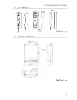
Page 31: ...CONFIGURATION AND SPECIFICATIONS 1 17 3 Handset NQW 261 4 Connection box NQD 2250 Unit mm Weight Approx 0 5 kg Unit mm Weight Approx 0 6 kg Mounting hole ...

Page 32: ...CONFIGURATION AND SPECIFICATIONS 1 18 5 Antenna Tuner NFC 2150 6 Junction Box NQD 2253 Unit mm Weight Approx 1 2 kg Unit mm Weight Approx 3 3 kg ...

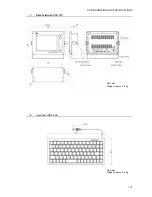
Page 33: ...CONFIGURATION AND SPECIFICATIONS 1 19 7 Data Terminal NDZ 227 8 Keyboard NDF 369 Unit mm Weight Approx 0 4 kg Unit mm Weight Approx 4 6 kg ...

Page 34: ...CONFIGURATION AND SPECIFICATIONS 1 20 9 AC DC Power Supply NBD 2150 Unit mm Weight Approx 9 8 kg ...

Page 35: ...CONFIGURATION AND SPECIFICATIONS 1 21 10 Battery Charger NBB 724 Unit mm Weight Approx 12 0 kg ...

Page 36: ...CONFIGURATION AND SPECIFICATIONS 1 22 11 Printer NKG 800 Desktop type Unit mm Weight Approx 3 7 kg ...

Page 37: ...CONFIGURATION AND SPECIFICATIONS 1 23 12 Printer NKG 91 Wall mount type Flush mount type Unit mm Weight Approx 1 5 kg Unit mm Weight Approx 0 8 kg Mounting hole Wiring hole side Wiring hole back ...

Page 38: ...CONFIGURATION AND SPECIFICATIONS 1 24 13 Printer DPU 414 Desktop type Unit mm Weight Approx 0 6 kg ...

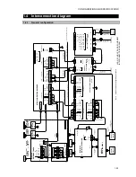
Page 39: ...BATT_LOW_TEMP GND 12 ACCESSRY 7ZCJD0348 1 5m R N AC IN DC 24V IN NBD 2150 AC DC POWER SUPPLY DC 24V OUT 1 4 3 1 2 1 DC_OPE DC_OPE DC_OPE FG GND GND Power source AC100V 220V 2 X 1 X 16mm 2 JIS DPYC 16 7ZCJD0347 1 5m OPTION OPTION DC24V IN DC24V IN POWER SUPPLY 2 1 TB101 ABOVE DECK NFC 2150 ANTENNA TUNER TX ANT RX ANT WKR RX ANT JQD 69C JOINT BOX RF_IN M A JJ M P 5 M P 7 6m WHIP ANTENNA NAW 60 JQD 6...

Page 40: ...ON BOX OPTION 1 NC DISP_PWR RS 485 B DISP_KEY RS 485 A NC GND DISP_LINE DISP_LINE GND GND DISP_PWR GND 14 NC DISP_PWR RS 485 B DISP_KEY RS 485 A NC GND DISP_LINE DISP_LINE 1 GND GND DISP_PWR GND EXTENSION 1 GND 14 1 OPTION 10 9 1 NC DISP_PWR RS 485 B RS 485 A NC GND DISP_LINE DISP_LINE GND GND DISP_PWR GND EXTENSION 2 14 10 9 9 10 EXT SP 1X 2 X 2 5mm2 JIS DPYC 2 5 4 X 2 X 0 75mm2 JIS TTYCS 4 TB12 ...

Page 41: ... EXTENSION BOARD GND GND GND GND TB21 TB22 TB23 NC D GPS RECEIVER IEC61162 1 OTHER SSB W FACSIMILE 1 X 2 X 0 75mm2 JIS TTYCS 1 1 X 2 X 0 75mm2 JIS TTYCS 1 ANTENNA MULTI COUPLER 1 X 2 X 0 75mm2 JIS TTYCS 1 2 X 1 X 25mm 2 JIS DPYCS 25 BATTERY DC24V 200Ah Dockyard Supply 2 X 1 X 25mm 2 JIS DPYCS 25 BATT_VOLT BATT_VOLT BATT_CURR BATT_CURR DC_OPE CHG_ALARM BATT_LOW_VOLT 1 U V AC IN BATT OUT NBB 724 BAT...

Page 42: ...CATIONS 1 28 1 5 Exploded views and wiring diagrams 1 5 1 NTD 2150 MF HF Transceiver 1 MF HF transceiver NTD 2150 exploded view Diagram no Name Bottom part Upper part Top plate Cover etc Packing Packing Pan head screw NB4 x Qty ...

Page 43: ...CONFIGURATION AND SPECIFICATIONS 1 29 ...

Page 44: ...CONFIGURATION AND SPECIFICATIONS 1 30 ...

Page 45: ...CONFIGURATION AND SPECIFICATIONS 1 31 ...

Page 46: ...Cable with connector Flat cable Flat cable Flat cable RF cable Note RF cable Diagram no Name RF cable RF cable RF cable Power cable Fan Note Fan Diagram no Name Cable with connector Note To CQD 2415 To CBD 2415 To CQD 2416 Right side view no side frame Top view no cover Left side view no side frame ...

Page 47: ...w no upper part Right side view no upper part Diagram no Name Cable with connector Power cable Power cable Power cable Power cable Note Cable with connector Diagram no Name Cable with connector Note To CAH 2415 To CQD 2415 To CAH 2415 To CMJ 2250 ...

Page 48: ...CONFIGURATION AND SPECIFICATIONS 1 34 1 5 2 NCM 2150 MF HF Controller 1 MF HF controller NCM 2150 exploded view ...

Page 49: ...scription Additionally when connecting the flat cables face up the blue tape and push the flat cable as far as it will go Locked state of the connector Unlocked state of the connector Flat cable Flat cable Flat cable W1 5ZCMD00018 W2 5ZCMD00046 from SP W7 7ZCJD0303 W3 7ZCJD0310 from LCD W6 7ZCJD0302A W4 7ZCJD0300A W5 7ZCJD0301 W8 7ZCJD0304 Release Lock ...

Page 50: ...nection diagram 3 MF HF controller NCM 2150 handset terminal HANDSET terminal No Name Description Connection point 1 PHONE 2 PHONE GND For connecting the handset 3 HOOKSW RXD Hook switch also for RXD 4 BIAS TXD Bias power supply 9 V 1 kΩ also for TXD 5 OCC For detecting connection 6 PTT PTT switch 7 MIC 8 MIC For connecting microphone NQW 261 or 7ZCJD0315 For PC connection Reference H 7ZCJD0315 Up...

Page 51: ...CONFIGURATION AND SPECIFICATIONS 1 37 1 5 3 NFC 2150 Antenna tuner 1 Antenna tuner NFC 2150 exploded view ...

Page 52: ...CONFIGURATION AND SPECIFICATIONS 1 38 2 Antenna tuner NFC 2150 wiring diagram ...

Page 53: ...IGURATION AND SPECIFICATIONS 1 39 1 5 4 NDZ 227 Data terminal 1 Data terminal NDZ 227 exploded view Name Diagram No Qty 1 DTE REFER TO A 2 MOUNT METAL REFER TO B 3 RUBBER MTT310999 2 4 KNOB BOLT MPTG30053 2 ...

Page 54: ... Qty 1 DTE 5 FRONT PANEL ASSYAAAAAAAAA REFER TO C 6 REAR CASE ASSY REFER TO D 7 COVER MTV304861 4 8 MAIN BODY LABEL MPNN46514 1 9 MODEL LABEL MPNN46516 1 10 OPERATION LABEL MPNN46517 1 11 VOID LABEL MPNN46515 1 12 LABEL MPNN44289 1 13 PT SCREW BRTG09223 12 ...

Page 55: ...IGURATION AND SPECIFICATIONS 1 41 B Name Diagram No Qty 2 MOUNT METAL 14 MOUNT METAL MTB396846 1 15 DIVIDED METAL MTB396847 1 16 RUBBER VIBRATION ISOLATOR MTV304863A 2 17 COUNTERSUBK HEAD SCREW BRTG09152 4 ...

Page 56: ...FRONT PANEL ASSY 18 FRONT PANEL ASSY REFER TO E 1 19 LCD BRACKET ASSY REFER TO F 1 20 MF HF COVER MTV304859 1 21 USB COVER MTT313662 1 22 KEY RUBBER MTT313667 1 23 LIGHT PIPE MTV304860 1 24 USB I F BOARD CQD 3227 1 25 PT SCREW BRTG09224 19 26 PT SCREW BRTG09223 2 ...

Page 57: ...ASE MTV304858 1 28 CONNECTOR MOUNT METALAAAA MTB396778 1 29 GASKET MPPK31570 1 30 POWER CONNECTOR 1 31 PAN HEAD SCREW BSNB04020B 1 32 COUNTERSUBK HEAD SCREW BSSK03008R 3 33 WASHER BSFW04000B 3 34 NUT BSHN04000W 1 35 NUT BSLN04000W 1 36 WING NUT BSBN04000B 1 37 SPRING WASHER BSSW04000S 1 ...

Page 58: ...CONFIGURATION AND SPECIFICATIONS 1 44 E Name Diagram No Qty 18 FRONT PANEL ASSY 38 FRONT PANEL MTV304857A 1 39 FILTER MTT313655 1 40 GASKET MPPK31571 2 41 GASKET MPPK31572 2 ...

Page 59: ...AAAAA 42 LCD BRAKET MTB396777 1 43 BRASS SPACER BRBP06614 4 44 SPRING WASHER BSSW03000S 4 45 SPACER BRBP05062 1 46 TAPPING SCREW BRTG09751 1 47 PAN HEAD SCREW BSNB03006R 15 48 COLOR LCD CCN 3227 1 49 PROCESS CIRCUIT CDC 1346B 1 50 INTERFACE UNIT CMH 3227 1 51 LCD I F BOARD CQC 1262 1 ...

Page 60: ...terminal NDZ 227 wiring diagram Name Diagram No Qty 1 FLAT CABLE 7ZCJD0365A 1 2 CABLE WITH CONNECTOR 7ZCJD0389A 1 3 FLAT CABLE 7ZCJD0364A 1 4 CABLE WITH CONNECTOR 7ZCJD0332B 1 5 CABLE WITH CONNECTOR 7ZCJD0363A 1 6 CABLE WITH CONNECTOR 7ZCJD0330B 1 ...

Page 61: ...ettings when two controllers are connected see 2 2 2 2 1 RS 485 signal line terminator settings of the installation manual z For printer settings see the concerned sections of the instruction manual 10 3 Printer NKG 91 or 10 4 Printer NKG 800 Additionally regarding DPU 414 printer see the DPU 414 OPERATION MANUAL in that printer package z For details on the controller setup menu see section 2 2 z ...

Page 62: ... Inmarsat C in parallel while operating the JSS 2150 on DC power Single Disable parallel Inmarsat C operation Dual Enable parallel Inmarsat C operation Set dual if the ship has an emergency generator Single F1 2 4 2 BATT use set Is a printer connected Yes Set 7 6 Option No 7 Option settings To use a printer set 7 6 1 Connection to SerialPRN or NKG 800 Set the other settings Data out Baudrate Flow ...

Page 63: ...r the following items 1 Status information Equipment settings 2 Maintenance information Software version 3 Alarm history System alarm info 1 ON 2 ON 3 ON F1 4 Remote maintenance 11 AME settings Set to ON if using AME OFF F1 2 1 3 AME 13 User channel registration Before setting checking the transmission power register frequently used channels as user channels None 7 4 User channels 12 Tx power sett...

Page 64: ...Menu F1 3 1 Address z Connectivity settings for DMC or simple AME Menu F1 2 1 1 DMC z AME connectivity settings Menu F1 2 1 3 AME The following can be set as necessary Caution Setting GPS alarm to off means non compliance with international standards ITU R recommendation Do not set it off except for special ships Additionally setting ATU use to off means the invalidation of all DSC functions inclu...

Page 65: ...lowing screens appear But this is not a malfunction The screens no longer appear after setting correctly and restarting z Unregistered MMSI alarm ENT z Controller address duplication alarm ENT Note2 On the controller address duplication alarm when a controller is entered a new address that controller is restarted automatically but another one is not restarted So turn off on the equipment immediate...

Page 66: ... the menu screen use the jog dial to scroll past 0 Back to display the menu for the field maintenance mode Display is also possible by selecting the item numbers on each menu For example to select F1 1 Registration press the MENU Æ FUNC Æ 1 Æ 1 keys 2 2 2 Exiting the field maintenance mode The field maintenance mode is exited when the equipment enters sleep mode Note When two controllers are conne...

Page 67: ...SETUP AND ADJUSTMENT 2 7 2 2 3 Menu tree ...

Page 68: ...SETUP AND ADJUSTMENT 2 8 ...

Page 69: ...he screen above displays the screen below z Move the cursor to the right of the items under 2 Serial number on the screen above and then enter the serial number z After displaying the letters such as BS using the jog dial press ENT 2 2 4 3 DMC AME settings Configure the connectivity settings if NCH 321A DMC or AME are connected Caution Setting 2 GPS to off on this menu does not sound an alarm when...

Page 70: ... Power operation settings Configure the power operation settings to detect DC operation status with the DC_OPE signal using the NBD 2150 AC DC power unit z AC DC detection Note1 To detect if operating in DC Valid To not detect if operating in DC Invalid z BATT use set Note2 To run in parallel with Inmarsat C in DC Dual To prohibit Inmarsat C use in DC Note3 Single Note1 To detect the condition if ...

Page 71: ...ctory default Note The equipment operates as follows when left idle in the field maintenance mode A popup screen appears in the lower left of the menu displayed and then returns to status display if left idle for 10 seconds When left idle on the status display and the time set for the Maintenance mode off timer has expired the popup screen on the right appears If left idle for 1 minute the equipme...

Page 72: ...t used After self diagnosis 22 WKR_MODEM self diagnosis information After self diagnosis 23 Controller 1 2 3 self diagnosis information After self diagnosis 24 Spare unit self diagnosis information Not used After self diagnosis 25 DISTRESS sent information After DISTRESS sent 26 EQP info 2 DTE1 2 3 1 hour Status information 28 DTE1 2 3 alarm information 60 seconds 2 Production technology info barc...

Page 73: ... diagnosis detail Used when self diagnosing at the equipment level For details refer to the explanation later z TX settings Used when adjusting the radio mainly transmitter For details refer to the explanation later z RX settings Used when adjusting the receiver For details refer to the explanation later z Controller MIC gain Adjust the MIC gain of the handset within a range of 1 to 32 levels Note...

Page 74: ...Data output is as follows For AME CTALR 999 hh CR LF is output For DMC after RDY and DRA are turned on for 3 seconds DAL is turned on for 3 seconds At that time MF HF DISTRESS and MF HF DSC lamps and buzzers operate respectively During this testing no transmission is occurred For Remote maintenance PJRCM CT 4 cxxx cxxx cxxx cxxx cxxx cxxx cxxx cxxx cxxx hh CR LF is output Note cxxx is the version ...

Page 75: ...nd4 Out Band4 Tune Band4 Tune Band5 Output Band5 Out Band5 Input Band5 In Band6 Output Band6 Out Band5 Tune Band5 Tune Input voltage Input volt Band6 Input Band6 In Band6 Tune Band6 Tune zTRX zMODEM Item Message Item Message ALL ALL ALL ALL Memory Memory Memory1 Memory1 Digital CKT Digital CKT Memory2 Memory2 BK port BK port Memory3 Memory3 PLL lock PLL lock PLL lock PLL lock Band1 TX output Band1...

Page 76: ...sing as a SSB radiotelephone Note The speech processor is a function that increases the average Tx power Normally controls peaks with ALC and compresses the gain of small signals When using this function controls peaks with a limiter so gain is not affected and the average Tx power is increased This function is available in TEL and H2B modes z RBK duration Set the time until RBK automatically turn...

Page 77: ...z 1785Hz Dot TLX 1615Hz 1785Hz Dot CW setup unnecessary z TX power Can be set between 0 5 to 200 0 of typical 100 Note1 The upper and lower limits might be refused by the PA limiter Note2 TX power can be set at 0 5 steps z TX Starts transmitting by the conditions above During the transmission this handling menu changes to Stop Press ENT again to stop the transmission According to the communication...

Page 78: ... of typical 100 Note1 The upper and lower limits might be refused by the PA limiter Note2 TX power can be set at 0 5 steps z TX Starts transmitting by the conditions above During the transmission this handling menu changes to Stop Press ENT again to stop the transmission According to the communication mode the PTT or CWKEY is available During the transmission PA voltage Vc PA current lc antenna cu...

Page 79: ...he TX power adjustment screen and or the frequency of TCXO CAUTION Use F2 3 3 Calibration menu only when having a margin of error obviously z Ic meter Adjust the value displayed for the PA current meter within a range of 99 to 99 When entering a value with the numeric keypad the of can be entered with 1 and the with 2 same below z Vc meter Adjust the value displayed for the PA voltage meter within...

Page 80: ...etween 20 to 78 dBuV Note The factory default is 40 dBuV Additionally it can be set to off to ignore the channel busy But normally set any value here z RF through Use a wide band BPF 1 6 30MHz ON Use a normal BPF for each band OFF Note The factory default is OFF If there is a external system that uses a common receiving antenna when scanning using a normal BPF that system may experience interferen...

Page 81: ...e User items BATT use set RBK duration TX delay Model power ATU setting RX antenna AC DC detection z TRX data The selected content below is initialized for TRX stored information Mode CH TRX Frequency AGC ATT NR SQL CW BW User All TRX stored information All Note The following are initialized when All is selected The above user items Speech processor AGC setting RX busy RF through z MODEM data The ...

Page 82: ...hen All is selected The above user items Controller settings MIC gain z Alarm log Initializes the system alarm history z Channel data Initializes all user channel information name type mode TRX frequency CH power Scan speed z All data The selected content below is initialized for all units User information for all units User All information for all units All Remarks Self ID MMSI is not initialized...

Page 83: ...the connected notebook PC from 38 4 k 57 6 k or 115 2 k z Connector Select the connector for connecting the notebook PC Controller handset Front Controller rear Dsub9pin Rear z Target unit Select the equipment to be upgraded Controller Controller Unit inside the transceiver Transceiver Note When upgrading the unit inside the transceiver select Transceiver and then select the target unit PA TRX or ...

Page 84: ...SETUP AND ADJUSTMENT 2 24 ...

Page 85: ...osis of each unit 7 Check GPS connection Longitude and latitude display matches GPS display 8 Check of 2 controllers operation Individual addresses and RS 485 terminator settings If existing 2 controllers 9 Check basic operation LCD settings frequency settings antenna tuning TEL CW transmission 10 Check Tx power and frequency Tx power and transmission frequency 11 Check antenna VSWR Antenna VSWR A...

Page 86: ... into the board connectors Are the flat cable W4 and power cable W5 in the NTD 2150 securely inserted into the board connectors Is the coaxial cable between the transceiver s Tx power TX ANT and the antenna tuner OK Check the cable itself for shorts between the central conductor and the shielding if the central conductor is broken etc Is any cable caught between the upper part and bottom part of t...

Page 87: ...operation Does pressing the DIM key switch the brightness of the LCD Does pressing the PRW CONT key adjust the contrast of the LCD Can the frequency be set with the jog dial and numeric keypad or can the antenna be tuned to all bands for example 4100 0 kHz for the 4M band Check that all the keys except the DISTRESS key function When the squelch is off can the speaker volume be adjusted by the RF G...

Page 88: ...C key and press 0 to display 1 DSC non distress call Enter the MMSI of the objective station coast station or other ship being called in Address As necessary enter the call frequency in Calling FRQ Default 2187 5 kHz Move the cursor to Call and press ENT to transmit a DSC test call Once a response from the objective station has been received check that that message displays as Received safety mess...

Page 89: ...ON 3 5 Then while retightening all screws to ensure they are securely tightened check that the coaxial and other cables are securely connected 3 1 2 17 Power off Turn the transceiver s power breaker off and exit field maintenance mode ...

Page 90: ... each controller Menu F1 3 1 Address MMSI lost appears MMSI is not registered Register the MMSI assigned by the supervising authority Menu F1 1 1 ID setup Barcode number lost appears The controller s production technology information is missing Replace CDJ 3775 This controller s SIO error appears RS 485 line error CTRL 485 test error Check wiring between the NCM 2150 and NTD 2150 Replace CMV 3775 ...

Page 91: ... error has occurred The screen above appears when upgrading by connecting a notebook PC to connector J105 Dsub9 on the CAH 2415 PA UNIT board Connecting a notebook PC to a controller displays the following upgrade screen Upgrade screen after connecting a notebook PC to a controller Refer to the explanation later for details on the upgrade environment and instructions Transceiver Check sum comparin...

Page 92: ...mory1 EEPROM1 operation OK Normal NG Error Replace EEPROM1 IC102 Memory2 EEPROM2 operation OK Normal NG Error Replace CAH 2415 Band1 Output 2200 kHz output value Band2 Output 4200 kHz output value Band3 Output 6300 kHz output value Band4 Output 8400 kHz output value Band5 Output 16800 kHz output value Band6 Output 26200 kHz output value OK Normal NG Error Check RF cable W5 between CMN 2250 and CAH...

Page 93: ... Check wiring between the NCM 2150 and NTD 2150 Check W11 W12 wiring in NTD 2150 Replace CMV 2150 Replace CMN 2250 LCD LED Screen and ALM lamp display operation Check visually if every dot and red and green ALM lamp alternately work normally for 3 seconds DONE Replace CDE 3770 LCD Replace CCK 3775 LED Speaker Sound circuit operation Check that a single tone sounds Press ENT on the popup screen to ...

Page 94: ... wiring between CBD 2415 and CAH 2415 Replace CAH 2415 091 PA EEPROM Detected a memory error Replace EEPROM1 IC102 Replace CAH 2415 017 ATU ATU lost Detected a serial communication error with the tuner Check wiring between the NFC 2150 NQD 2253 and NTD 2150 Replace CFG 2150 018 ATU High voltage Detected a high voltage 3 5 kV or more in antenna output Re tune or reduce output Check Antenna 019 ATU ...

Page 95: ...ide the NTD 2150 such as the W12 between the CMN 2250 and CAH 2415 Replace CMN 2250 Replace CAH 2415 050 WKR MODEM MODEM lost Detected a serial communication error with WKR MODEM Check wiring inside the NTD 2150 such as the W14 between the CMJ 2250 and CAH 2415 Replace CMJ 2250 Replace CAH 2415 2 Controller alarms No Location Message Description Countermeasure 035 Controller CTRL1 RBK OC Detected ...

Page 96: ...with the EXT KEY of controller 2 Check if was started up while EXT KEY on EXT MODEM was on Check W5 in the NCM 2150 Replace CMV 3775 051 Controller CTRL1 lost Detected a serial communication error on controller 1 Check wiring between the NCM 2150 No 1 and NTD 2150 Replace NCM 2150 No 1 052 Controller CTRL2 lost Detected a serial communication error on controller 2 Check wiring between the NCM 2150...

Page 97: ...nal My OTH DTE USB IC Detected the SPI communication error at the USB circuit of the data terminal connected to the controller ID 1 Note My or OTH indicates the relationship between that data terminal and the controller displaying this alarm Replace CMH 3227 Replace CDC 1346B 063 Data terminal My OTH DTE USB IC Detected the SPI communication error at the USB circuit of the data terminal connected ...

Page 98: ...signal transmission circuit malfunction Check AF OUTPUT on Menu F2 2 5 Controller Check handset connector W3 inside CMV 3775 CMN 2250 and NCM 2150 W11 and W12 inside NTD 2150 and controller connection cable replace if necessary 5 Reception level is poor Check antenna position Change receiving antenna TX ANT Ù WKR RX ANT Menu F2 4 1 RX antenna Connect a dedicated reception antenna to the NTD 2150 A...

Page 99: ...the equipment automatically switches to the backup DC power input when AC power is cut 5 Check registration ID Check the ship s MMSI and the equipment s manufacture number Menu F1 1 Registration 6 Check basic operation Check basic operations of the equipment including the power on and off switch adjust frequencies with the jog dial RF GAIN and VOL knob operation jog dial operation and transmission...

Page 100: ...al output by pressing ENT at Stop button of 2 Output 4 1 3 Measuring the test tone Measure the test tone 1500 Hz Note 1400 Hz for Korea mode used in TEL mode as follows Note Transmission occurs while outputting a test tone Before measuring the test tone always check the radio frequency is free Then perform that measuring for as short a time as possible 1 Connect the frequency counter to the extern...

Page 101: ...源 部 PS UNIT CQD 2415 接 続 端 子 部 TERMINAL UNIT CQD 2416 拡 張 基 板 EXTENSION BOARD To connect the external units such as RMS NTD 2150 筐 体 CHASSIS M P 7 付 属 コ ネ ク タ COAXIAL CONNECTOR 2pcs 7ZPJD0461 操 作 カ ー ド BRIDGE CARD JPN 7ZPJD0460 MPNN46153 警 告 ラ ベ ル WARNING LABEL 7ZPJD0065 レ ジ ス タ リ ス ト WARRANTY LIST Basic configuration JSS 2150 MF HF 無 線 装 置 MF HF RADIO EQUIPMENT NTD 2150 MF HF ト ラ ン シ ー バ MF HF TR...

Page 102: ...50 筐 体 CHASSIS MPNN45689 舵 輪 マ ー ク MED PLATE NCM 2150 MF HF コ ン ト ロ ー ラ MF HF CONTROLLER MPNN45781A シ リ ア ル 銘 板 NAME PLATE NQW 261 ハ ン ド セ ッ ト HANDSET Includes the cradle 7ZCJD0343 コ ン ト ロ ー ラ 用 ケ ー ブ ル ATTACHED CABLE L 5m CFG 2150 同 調 部 MATCHING UNIT NFC 2150 筐 体 CHASSIS HC ESV 8X20A WG 20 0 18 制 御 ケ ー ブ ル CONTROL CABLE L 5m 7ZCJD0045 RF ケ ー ブ ル RF CABLE L 5m Continued Continued Continued NFC 215...

Page 103: ...MANUAL JPN 7ZPJD0500 CDC 1346B ル パ ン ボ ー ド PROCESS CIRCUIT CMH 3227 I F ユ ニ ッ ト INTERFACE UNIT CCN 3227 LCD ユ ニ ッ ト COLOR LCD UNIT CQC 1262 LCD I F ユ ニ ッ ト LCD I F UNIT NDZ 227 デ ー タ タ ー ミ ナ ル DATA TERMINAL CQD 3227 USB I F ユ ニ ッ ト USB I F UNIT NDF 369 キ ー ボ ー ド KEYBOARD 7ZCJD0388 DTE 信 号 ケ ー ブ ル DTE CABLE L 1 5m 7ZCJD0419 DTE 電 源 ケ ー ブ ル DTE POWER CABLE NKG 800 プ リ ン タ PRINTER Desktop parallel pr...

Page 104: ...UPPLY NBB 724 充 電 器 BATTERY CHARGER 7ZCJD0347 AC IN ケ ー ブ ル AC IN CABLE For NBB 724 7ZCJD0348 BATT OUT ケ ー ブ ル BATT OUT CABLE For NBB 724 7ZCJD0349 BATT ケ ー ブ ル BATT CABLE For NBB 724 NQD 2250 コ ン ト ロ ー ラ 接 続 筺 CONNECTION BOX CQD 2250 接 続 端 子 板 CONNECTION BOARD NQD 2250 筐 体 CHASSIS MPBC42957 フ ラ ッ シ ュ マ ウ ン ト パ ネ ル CONSOLE MOUNTING KIT For NCM 2150 MPBX44354 U 字 架 台 CONTROLLER BRACKET For NCM 2150...

Page 105: ...PRINTER Desktop type 7ZCJD0257C プ リ ン タ 電 源 ケ ー ブ ル PRINTER PS CABLE For DPU 414 6ZCAF00252A プ リ ン タ 用 紙 ROLL PAPER For DPU 414 NKG 800 プ リ ン タ PRINTER Desktop parallel printer See note2 below 6ZCSC00407 プ リ ン タ ケ ー ブ ル PRINTER CABLE For NKG 800 6JNKD00100B プ リ ン タ 電 源 ケ ー ブ ル POWER CABLE For NKG 800 5ZPCM00006 プ リ ン タ 用 紙 ROLL PAPER For NKG 800 NKZ 224 ア ン テ ナ 切 替 器 ANTENNA CHANGER NQE 2150 AC DC...

Page 106: ... etc Category Model Name JPN ENG Model Name JPN ENG Model Name JPN ENG Note 7ZZJD0072 ラ ッ ク マ ウ ン ト キ ッ ト RACK MOUNT KIT For NBD 2150 7ZZJD0073 ラ ッ ク マ ウ ン ト キ ッ ト RACK MOUNT KIT For NBB 724 NQD 2724 端 子 台 ボ ッ ク ス TERMINAL BOX For NBB 724 Continued ...

Page 107: ...aper guide board 94447 2410 1 3 LF knob 94410 2090 1 4 Top enclosure 94450 2001 1 13 Indicator plate 94478 2010 4 2 Print head unit SP 24090AI Not shown in the following figure 10 1 Paper holder 84930 2074 1 10 2 Cover 94447 2030 10 3 Paper guide G 94447 2300 10 4 Paper guide shaft 84930 2440 10 5 Spring B 94447 2421 2 peaces for 1 unit 10 6 Guide ring 94447 2075 2 peaces for 1 unit 10 7 Spring A ...

Page 108: ...Maintenance 4 10 ...

Page 109: ... Default 2 182 0 kHz Not portable AGC USB LSB Slow Fast OFF Default Slow Not portable AGC CW Slow Fast OFF Default Fast Not portable Receive ATT 0 db OFF 6 dB 12 dB 18 dB Default 0 dB off Not portable NR NR1 NR2 BC OFF Default Off Not portable SQL 0 to 100 Default 0 Not portable BW Narrow Wide Default Narrow Not portable Speech proc On off Default Off Not portable AGC characteristics Normal flat D...

Page 110: ...el group attribute Default TEL Transferable by data transfer Rx FRQ RX frequency of the user channel table Transferable by data transfer Tx FRQ TX frequency of the user channel table Transferable by data transfer Mode User channel communication mode Default TEL Transferable by data transfer Connection Printer and other connection settings Default None Not portable Data out Printer output mode auto...

Page 111: ...list Not portable Sunspot number Sunspot numbers for MUF calculation Not portable LCD LED dimmer LCD LED brightness value Default 13 Not portable LCD LED dimmer button setting Maximum Typical Minimum dimmer settings Not portable Screensaver setting Function ON OFF Default ON Starting time Default 3 Not portable Display color pattern Basic coloring pattern Default Ocean day Not portable User define...

Page 112: ...he baudrate is 38 4kbps the approximate time required to upgrade each unit is as follows CAH 2415 PA UNIT 3 minutes CMN 2250 TRX UNIT 5 minutes CMJ 2250 WKR MODEM 14 minutes NCM 2150 MF HF CONTROLLER 7 minutes Note 5 Regarding the upgrading for the data terminal see the description of Data terminal maintenance mode Preparing to upgrade Prepare the following items before doing an upgrade Notebook P...

Page 113: ...roller handset Front Controller rear Dsub 9 pin Rear Target unit Select the equipment to be upgraded Controller Controller Unit inside the transceiver Transceiver 4 Press ENT on Execute and the OK to upgrade popup screen appears Select OK and press ENT to display the following screen that indicates the equipment is waiting for a software upgrade from the notebook PC The following is an example whe...

Page 114: ... pull down menu Note that if a controller program error is occurred and the controller upgrading is performed on the boot program displayed as shown in the following right always select CNT ID 1 regardless of the address of that controller PA is selected for this example Startup screen of the boot program Controller Check sum comparing error Please re install the program again now Target unit Cont...

Page 115: ...Maintenance 4 17 8 Press the file select button and select the software to upgrade After selecting a file the file name appears as follows in the file name field ...

Page 116: ...roblem with the JSS 2150 reception settings discussed previously or the cable connection at this time the following error message appears Correct the problem and press Write start again 10 After the upgrade starts the percent and progress of the transfer status is displayed as follows ...

Page 117: ...he controller shows NB Reconnect the DTE cable and press ENT here Then reconnect the data terminal cable and press ENT key of the controller to restart the system 12 Clicking the X in the window closes the PC application software Note 1 The Restart the JSS 2150 radio dialog box is displayed Normally click No here Note 2 To continue upgrading other units repeat the procedure above ...

Page 118: ...ceiver Caution Controllers cannot be upgraded with this procedure Upgrade procedure 1 Open the cover of the transceiver 2 Connect an RS 232C straight cable to the J105 connector Dsub 9 on the CAH 2415 PA UNIT to configure as shown below 3 Start the JSS 2150 in user or maintenance mode RS 232C straight cable JSS 2150 Notebook PC COM port PA UNIT CAH 2415 Dsub 9 on board ...

Page 119: ...x x exe discussed previously 5 Select the RS 232C Com port on the notebook PC and select 38400 bps as the fixed communication speed In this case do not select 57600 bps or 115200 bps 6 Select the target unit PA TRX or MODEM to upgrade by the Target pull down menu PA is selected for this example ...

Page 120: ...Maintenance 4 22 7 Press the file select button and select the software to upgrade After selecting a file the file name appears as follows in the file name field ...

Page 121: ...s the display on the controller s LCD is as follows 2 If there is a problem with the JSS 2150 reception settings or the cable connection at this time the following error message appears Correct the problem and press Write start again Software upgrade mode Target unit PA Baudrate kbps Connector ...

Page 122: ... When Percent reaches 100 Writing processing Complete appears in Msg box and the upgrade is finished 12 Clicking the X in the window closes the PC application software Note 1 The Restart the JSS 2150 radio dialog box is displayed Normally click Yes here Note 2 To continue upgrading other units repeat the procedure above ...

Page 123: ... maintenance mode showing the following items 1 Initial setting Serial number confirmation 2 Maintenance check Self diagnosis such as internal external circuits 3 Data initialize Initialization to the factory default settings 4 Software upgrade Upgrading procedures via USB memory or SIO 5 5 5 Operate the data terminal in the maintenance mode 6 6 6 To finish the maintenance mode restart the data te...

Page 124: ... of the green color Blue Check the dots of the blue color White Check the dots of the white color Black Check the dots of the black color Yellow Check the dots of the yellow color Magenta Check the dots of the magenta color Cyan Check the dots of the cyan color Test Check the dots while changing tones 2 Screen JRC Check the power up screen Printer Outputting the test message Serial1 Outputting the...

Page 125: ...s follows Communication speed 38 4 kbps Data length 8 bits Stop bit s 1 bit Parity None This menu is available only when the USB memory is selected as the input port And up to five files in the USB memory are listed to select one file Note that the folder name and the filename should be followed below NDZ 227J NDZ227J_xxxx bin xxxx 4 digits of the version number 1 Input port USB memory 1 1 1 After...

Page 126: ...l to the receiving condition 3 3 3 Start sending the object file from the external computer with the upgrade software NDZ 227 FLASH WRITER as shown at right During receiving the file displays the message of Now upgrading the data terminal blinking as shown at right 4 4 4 After completing the software upgrade starts the countdown as shown at right and the data terminal restarts after 5s automatical...

Page 127: ...番号 Software maintenance number Ver Ver BJ BJ 機器製造番号 Unit serial No BJ BJ MF HF コントローラ MF HF Controller NCM 2150 ソフトウェアメンテナンス番号 Software maintenance number Ver Ver BJ BJ 機器製造番号 Unit serial No BJ BJ データターミナル Data terminal NDZ 227 ソフトウェアメンテナンス番号 Software maintenance number Ver Ver 機器製造番号 Unit serial No BC BC アンテナチューナ Antenna tuner NFC 2150 ソフトウェアメンテナンス番号 Software maintenance number Ver Ver 工事日 Servic...

Page 128: ...Maintenance 4 30 ...

Page 129: ...D GND GPS_RX B GPS_RX A BK BK RBK GND GND GND B1 1 2 GND GND EXT_KEY SEL_BK RBK RBK GND GND To WKR MOMEM UINT 20 25 10 1 15 5 RF_IN WKR_RX_IN DC_OPE DC_OPE GND GND 10 1 15 5 20 DISP_KEY GND 10 1 15 5 20 10 1 15 5 20 10 1 15 5 20 20 25 10 1 15 5 SEL_BK 1 DMC_SEL DMC_DRQ DMC_PWR DMC_RDY DMC_DRA DMC_DAL GND DMC_DAS DMC_OAL DMC_OAS 422_RX A AME_RX A AME_TX A AME_RX B AME_TX B GND RMS_TX A RMS_TX B 422...

Page 130: ...R ALM Ckt RBK ERR LOAD ALM LPF2 LPF6 74VHC238 K ANT TX FWE WRITE RES CONT TYPE1 2 3 AVR PA ON ISL3172 485 ERR 2SC5337 PA ERR ROM1 CS RE 485 RX ANT Vc Ic SENSOR ALM Ckt RD16HHF1 2 OC A RX OUT FAN FAN FAN DA KEY BIAS 2 RS 232 TUNE KEY MODEM RST TRX RST PA KEY AND PT PT PA MUTE PT PT DC PT TLP181GR TLP181GR TLP181GR TLP181GR RF VF RF VR ANT CURR AVR PA9V AVR PA5V PA BIAS 2SC2510A 2 WKR RX IN 50Ω SERI...

Page 131: ...ODEM TUNE KEY TXD CONT MNT RXD TRX TXD MODEM TXD DUP TXD EXT CLK PCM1742 BR25L640 AN7709SP NJM2374 SPI RX ANT HARD VER SSB 3bit M25P40 TL3414AI AD9951 MMBFJ310 X4 SN74CBT3125 ISL3172EIBZ NJM2737 ATT 6dB RX BPF8 PLL DUC 400MHZ 2SC4116 1 2 BF998R MB15E03 2SC3356 X2 2SC3356 2SC3356 2SC3356 2SC3356 400MHz RX BPF1 BAND 90 399 9kHz 400 1 599 9kHz 1 600 3 199 9kHz 3 200 6 099 9kHz 6 100 10 499 9kHz 10 50...

Page 132: ...APPENDIX 5 4 5 1 4 CMJ 2250 WKR MODEM UNIT DMC TRX DIODE SWITCH DIODE SWITCH ...

Page 133: ... IRQ0 A D S7 IC control P_BACK P_BACK VOL SQL 12V 5V AVR 26V DISP_PWR 5V 3 3V 26V 1 5v Fuse 6 5V 12V 150Ω 150Ω ADD 0Ω ADD SP IC control ALM_LED ALM_LED ALM_LED 232C drv SCIF1 SCIF0 RS485 I F RS232 I F F R_SEL TXD BIAS RXD HOOKSW OFF_HOOK DET232 Key Brightness Key Brightness Key Brightness Contrast SQL_GAIN CONTROL UNIT CDJ 3775 PT Temp AVR DET422 3 3V RS485SEP PWR_CONT RS485 drv RS485DRV RS485SEP ...

Page 134: ...APPENDIX 5 6 5 1 6 NDZ 227 DATA TERMINAL ...

Page 135: ...APPENDIX 5 7 5 1 7 NFC 2150 ANTENNA TUNER CFG 2150 MATCHING UNIT SWR_VF L_PHASE SWR_VR LOW_R 9 6 6 A D A D 15 TUNE KCS I 2C NTD 2150 MF HF RADIO EQUIPMENT TX ...

Page 136: ...搬送波電力 Carrier suppression 52 9 dB 70 8 dB 50Ω 1600 3999 9kHz 100 75W 150 100 75W 感度 3 1 2 1 Sensitivity A1A F1B 0 5kHz以下 or less 測定周波数 Measured at 8414 5kHz Mode F1B J3E 3 0kHz以下 or less 測定周波数 Measured at 8291 0kHz Mode J3E 1 5kHz 4 5kHz 31dB以上 or more 4 5kHz 7 5kHz 38dB以上or more 7 5kHz 43dB以上 or more REL to below PEP 測定周波数 Measured at 4100 0kHz Mode J3E 変調周波数 MOD Frequencies 700 2500Hz A1A F1B 4 ...

Page 137: ...APPENDIX 5 9 ...

Page 138: ...APPENDIX 5 10 ...

Page 139: ...APPENDIX 5 11 ...

Page 140: ...APPENDIX 5 12 ...

Page 141: ...APPENDIX 5 13 ...

Page 142: ...APPENDIX 5 14 ...

Page 143: ...APPENDIX 5 15 ...

Page 144: ...APPENDIX 5 16 ...

Page 145: ...APPENDIX 5 17 ...

Page 146: ...APPENDIX 5 18 ...

Page 147: ...APPENDIX 5 19 ...

Page 148: ...APPENDIX 5 20 ...

Page 149: ...APPENDIX 5 21 ...

Page 150: ...APPENDIX 5 22 ...

Page 151: ...APPENDIX 5 23 ...

Page 152: ...APPENDIX 5 24 ...

Page 153: ...APPENDIX 5 25 ...

Page 154: ...APPENDIX 5 26 ...

Page 155: ...APPENDIX 5 27 ...

Page 156: ...APPENDIX 5 28 ...

Page 157: ...荷時設定 インマルサットCモード To select the MF HF mode set the DIP switch on the back of the NDZ 227 as shown at right Factory default setting Inmarsat C mode b NDZ 227 に同梱のボイドシールを右記のように貼付 してください Put a void sticker included with the NDZ 227 as shown at right 2 2 2 品名シールの貼付 Sticking the model name NDZ 227 に同梱の MF HF シールを右記のように貼付 してください Put the MF HF sticker included with the NDZ 227 as shown at right 3 3 3 起動画面...

Page 158: ... the gasket of the NDZ 227 Data terminal comes off fit it again as follows 1 1 1 パッキンの先端と末端をリアケース下側の切り欠き 中央を目印にして溝にはめる Insert the start and the end of the gasket in the slot making bottom center notch of the rear case a sign 2 2 2 矢印の方向に押し込みながら パッキンを末端まで溝 にはめる Insert the gasket in the slot until the end pushing it into the direction of the arrow ...

Page 159: ......
Page 160: ...ail AMSTERDAM Branch Telephone Facsimile e mail 31 20 658 0750 31 20 658 0755 service jrcams nl SEATTLE Branch Telephone Facsimile e mail 1 206 654 5644 1 206 654 7030 service jrcamerica com CODE No 7ZPJD0501 CODE No 7ZPJD0501 NOV 2010 Edition 1 JRC NOV 2010 Edition 1 JRC Not use the asbestos For further information contact URL http www jrc co jp ...

Reviews: