background image

24

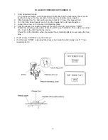
TO ADJUST BOBBIN THREAD SENSOR

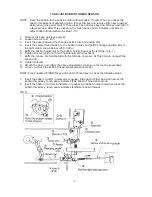
NOTE: Insert the bobbin to the bobbin holder without bobbin Thread. When you check the

bobbin thread sensor adjusting mode. (Press S/S key and reverse stitch key together
while turning the power switch, Then press The auto-look key and S/S key next with in
a few seconds. After This procedure, the touch panel (LCD) indicates numbers to
adjust bobbin thread sensor as step 1-13.)

1.

Remove the base unit (see page 6).

2.

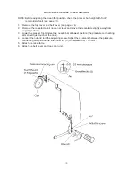
Loosen screws A (2), B (1).

3.

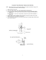
Insert the pacer between the change position arm and driving arm.

4.

Insert the empty thread bobbin to the bobbin holder, and pull the change position arm to
the right side A shown below. (200 - 300 g)

5.

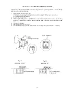
Buffs the bobbin holder unit to the bobbin holder topper at the left side. (Fig. 1)

6.

Tighten screws (2) (do not hold The solenoid with your hand).

7.

Buffs the convex of shielding plate to the left side of sensor. At This time do not push the
sensor rod.

8.

Tighten screw B.

9.

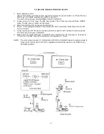
Aft ach the base unit. (After the above adjustment, make sure the touch panel shows

10  when you check the bobbin thread sensor adjusting mode.)

NOTE: Press needle UP/DOWN key and bobbin Thread key to check the following steps.

1.

Insert the bobbin (9.2mm in diameter or gauge) into bobbin holder and when press the
bobbin thread key, touch panel indicates (The bobbin Thread almost out).

2.

Insert the bobbin (10.3mm in diameter or gauge) into bobbin holder and when press the
bobbin thread key, touch panel indicates (sufficient bobbin thread).

Summary of Contents for MEMORY CRAFT 9000

Page 1: ...1 SERVICING MANUAL...

Page 2: ...rd unit 1 14 To change printed circuit board a board unit 2 15 Drawing for a board connectors front panel complete unit 16 To change board c and fuse 17 To change dc motor and belt tension adjustment...

Page 3: ...ighten the screws securely 4 Check if the face plate opens and closed smoothly Adjust the position of the face plate spring if necessary TOP COVER UNIT TO REMOVE 1 Remove the two screws A and raise th...

Page 4: ...TO REMOVE 1 Loosen the screw A and remove screws B C and the washer 2 Loosen the screw D completely and remove the belt cover unit TO ATTACH 3 Insert the belt cover in the front panel 4 Replace screw...

Page 5: ...move the base lid 3 Remove the two screws B and remove the bed cover unit Then pull out the connectors from the connector supporter and disconnect them TO ATTACH 4 Follow the above procedure in revers...

Page 6: ...move the 4 screws and the base unit TO ATTACH 4 Follow the above procedure in reverse Check the position of feed dog UP and DOWN NOTE 1 Set The base unit that the right side of knee lifter link 4 claw...

Page 7: ...Select straight stitch 1 and turn the hand wheel toward you to bring the needle bar to the lowest position see page 8 2 Loosen the setscrew and move the zigzag rod left or right to set the needle at...

Page 8: ...elect stitch pattern 2 2 Press stitch length stitch width key and set the needle position to 0 0 on the touch panel 3 Turn the hand wheel toward you until the point of the hook meets the right side of...

Page 9: ...4 Turn the hand wheel toward you and set the needle bar to the lowest position 5 In this condition If the setting mark on the feed lift cam is right under the center of the lower shaft Fig 1 loosen th...

Page 10: ...oward you slowly with your hand until the needle starts to swing A If higher than 8 2 mm loosen the setscrew and turn the upper shaft shield plate in direction A B If lower than 7 0 mm loosen the sets...

Page 11: ...e S S key to turn the hand wheel 2 to 3 rotations 2 Open the face plate and adjust the thread tension with a screwdriver in the direction of A to looser the tension B to tighter the tension 3 Close th...

Page 12: ...e mechanism for the knee lifter 1 Remove the top cover unit see page 3 2 Lower the presser foot lifter raise the needle bar to its highest position attach the foot A and lower the presser foot Make su...

Page 13: ...e screw and remove the threader plate Fig 1 TO ADJUST NOTE Use 11 needle to adjust the threader plate position 3 If the hook of the threader plate touches left or right side loosen the screw and adjus...

Page 14: ...screw A and loosen screws B C D 4 Pull out 17 connectors form the printed circuit board A board and printed circuit board F board Remove the front cover unit NOTE Pull out the LCD connector at the be...

Page 15: ...nector until connected Then attach to A board 5 Attach the printed circuit board A with 6 screws and insert the 2 flat cables to the connector then push down the clamp Make sure the inject button shou...

Page 16: ...Q X axis stepping motor for embroidery E Position sensor R Y axis stepping motor for embroidery F Inverter G Bobbin thread sensor H Feed dog up down switch I Lamp switch J Bobbin thread detector sole...

Page 17: ...unit TO CHANGE THE FUSE 6 After remove the board C case unit remove two setscrews to pull out the printed circuit board C 7 Replace the fuse in the fuse holder on board C If Fuse Fl 125V 2 SA is blown...

Page 18: ...the motor connector from A board unit and remove 2 screws Then remove the DC motor unit TO ATTACH 4 Pass the motor cord under the arm lib then attach the motor with 2 screws temporary as shown below 5...

Page 19: ...anel board A unit see page 14 2 Remove the cord guide see page 7 and the DC motor see page 18 3 Remove two connectors of transformer from C board case unit 4 Remove the three screws and pull out the t...

Page 20: ...REMOVE 1 Remove the belt cover see page 4 2 Cut the cord binder 3 Pull out the connectors from board A unit and board C case unit 4 Remove two set screws and change the receptacle machine socket unit...

Page 21: ...over board A see page 14 15 2 Loosen two screws A and remove A board fixing plate 3 Loosen four screws B and remove the LCD frame unit TO ATTACH 4 Follow the above procedure in reverse NOTE Check the...

Page 22: ...bring the needle bar to its lowest position 4 Loosen the screw on the presser bar shielding plate 5 Shift the presser bar shielding plate all the way to the right LCD shows OPEN 6 Rotate the shielding...

Page 23: ...play LCD shows OPEN only correctly adjusted Turn the power off to exit adjusting mode CLOSED Adjust the presser bar height with the embroidery foot and repeat steps 1 6 again NOTE Lower the presser fo...

Page 24: ...ight side A shown below 200 300 g 5 Buffs the bobbin holder unit to the bobbin holder topper at the left side Fig 1 6 Tighten screws 2 do not hold The solenoid with your hand 7 Buffs the convex of shi...

Page 25: ...the presser bar sensor connector from the board F Remove the cord from the cord guide and remove the sensor unit TO ATTACH 4 Follow the above procedure in reverse NOTE Make sure the sensor and shield...

Page 26: ...the BH foot R and lower the BH lever 4 Put a 1 6 mm gauge in between the sliding part of the automatic buttonhole foot and its end as shown 5 Loosen set screw B Move the sensor plate from right to lef...

Page 27: ...plate 2 Remove the snap ring 3 Pull out the BH lever unit TO ATTACH 4 Slide The BH lever unit without BH shielding plate onto the shaft as shown below and put the snap ring on the shaft 5 Attach the B...

Page 28: ...ll out the BH sensor connector from board F and pull out the cord from the cord guide 1 2 Then change the BH sensor unit TO ATTACH 4 To attach the BH sensor follow the above procedure in reverse NOTE...

Page 29: ...he machine a little and pry off the cover cap with a screwdriver as shown below 2 Loosen the two screws 3 If the drop feed finger does not fit into the notch in the drop feed knob when embroi dery sew...

Page 30: ...unit loosen screws and move the receptacle slightly away from original position 3 Lower the presser foot and set the needle bar at lowest position the pressure con necting arm should just touch on th...

Page 31: ...sounds at left right positions LCD shows CONTROLLER Buzzer sounds when foot controller is pressed fully and released LCD shows FOOT LEVER Buzzer sounds when foot controller is depressed and released L...

Reviews: