background image

Align

Align

Align

4 Louver Guides Installation:

• On side housing panels with J&D logo align indicated edges of louver guides, as shown below 
• Using the included 

#3 Phillips Bit from Bag 1 (Tools)

 and (5) #14-10 x 2” 

Screws from 

   Bag 2 (Part 3)

, secure each louver guide to the housing

22

Use hand tools ONLY

Use hand tools ONLY

4 Louver Installation:

• Assemble (16) 5/16”-18 x 7/8” 

Bolts

  and (16) 5/16” 

Washers from Bag 4 (Motor Key & 

   Louver Hardware)

• Using only hand tools 

(DO NOT USE IMPACT DRIVER)

 secure each louver to the louver 

   guides, as shown below

23

IS297-22F 

J&D Manufacturing • 6200 Hwy 12 • Eau Claire, WI 54701 • 1-800-998-2398 • www.jdmfg.com 

Page 14/27

Summary of Contents for AIRBLASTER 3 LOUVER

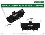
Page 1: ...4 Louver Bi Directional 3 Louver Uni Directional IS297 22F J D Manufacturing 6200 Hwy 12 Eau Claire WI 54701 1 800 998 2398 www jdmfg com Page 1 27 AIRBLASTER 3 LOUVER 4 LOUVER RECIRCULATION FANS ...

Page 2: ... Attaching Hanging Chain Kit Step 11 Site Requirements Step 12 Mounting Height Recommendations Step 13 Hanging Recommendations Step 14 Hanging Installation w Stabilizing Chain Harness Trimming Chain to Make Stabilizing Chain Harness Step 15 Stabilizing Chain Harness Assembly Step 16 Installing Stabilizing Chain Harness to Fan Step 17 How to use the Stabilizing Chain Harness to Hang Fan Step 18 Sit...

Page 3: ...98 2398 www jdmfg com Page 3 27 RECOMMENDED TOOLS SUPPLIES FOR INSTALLATION AND ASSEMBLY NOT PROVIDED PARTS LEGEND Chain Kit 4 Chains 8 Quick Links 1 Bolt Nut and Washer Set Safety Glasses Socket Wrench 1 2 Socket 3 4 Socket Impact Driver 1 2 Wrench 3 4 Wrench 10 ft lbs Torque Wrench 23 ft lbs Torque Wrench Bolt Cutter Bag 1 Tools 3 Phillips Bit Bag 2 Housing Bag 2 Part 1 28 5 16 18 x 7 8 Bolts Ba...

Page 4: ...bly Lay out the 4 venturi sections flat on the floor with the curve side of the sections facing up Assemble the motor mount brackets flat side down in between each venturi section 1 Using 28 5 16 18 x 7 8 Bolts from Bag 2 Part 1 and 28 5 16 18 Serrated Flange Nuts from Bag 2 Part 2 assemble the motor mount brackets and venturi sections Tighten only the bolts and nuts securing venturi sections Hold...

Page 5: ...e center of the housing panel and continue to slide housing panel until it is centered Repeat until all four sides have housing panels installed 3 Side Panels with Logo Installing Housing Corner Caps Place a housing corner cap onto the housing between 2 housing side panels assembled in the previous step Using the included 3 Phillips Bit from Bag 1 Tools and 6 14 10 x 2 Screws from Bag 2 Part 3 scr...

Page 6: ... 1 Tools and 6 14 10 x 2 Screws from Bag 2 Part 3 screw the corner to the panels Repeat until all four hanging brackets have been installed 5 Motor Installation NOTE 2 person lift is recommended for handling of 105lb motor Using the pallet the fan came on place the motor in the center between the pallet slats with the shaft facing up Place housing onto pallet curved side down Use scrap wood 2x4 s ...

Page 7: ... an aluminum housing care must be taken to not cross thread or strip out the motor mounting threads Once all motor mounting hardware has been hand started torque the bolts to 23 ft lbs using hand tools only 7 Prop Installation Insert the 1 4 x 2 Machine Key from Bag 4 Motor Key Louver Hardware into the keyway on the motor shaft Slide prop onto the keyed motor shaft until flush with end of motor sh...

Page 8: ...own below Using the included 3 Phillips Bit from Bag 1 Tools and 5 14 10 x 2 Screws from Bag 2 Part 3 secure each louver guide to the housing 9 If installing the 3 Louver AirBlaster proceed to Step 9 If installing the 4 Louver AirBlaster skip to Step 22 3 Louver Installation Assemble 12 5 16 18 x 7 8 Bolts and 12 5 16 Washers from Bag 4 Motor Key Louver Hardware Using only hand tools DO NOT USE IM...

Page 9: ...1 hanging chain to each mounting bracket using 1 quick link as shown below Secure connections by fully closing each quick link by rotating the barrel until opening is closed and barrel no longer turns 11 3 Louver Mounting Height Recommendations 13 Weight 350lbs Site Requirements Structure and anchor hardware not provided must be rated for 350lbs 12 Before proceeding review the angle recommendation...

Page 10: ...ations Take into account recommendations from Steps 12 13 and the below recommended angles of the fan and chains Hang fan Attach each chain end to structure using 1 quick link Secure by fully closing each quick link by rotating the barrel as shown in Step 11 NOTE To ensure fan does not distort or twist fan must be hung evenly and level from side to side as shown below If not hung correctly fan dis...

Page 11: ...il opening is closed and barrel no longer turns 17 IS297 22F J D Manufacturing 6200 Hwy 12 Eau Claire WI 54701 1 800 998 2398 www jdmfg com Page 11 27 Stabilizing Chain Harness Assembly Using the 1 Bolt Nut and Washer Set that was included with the Chain Kit bolt together one end of each chain as shown below 16 Trimming Chain to Make Stabilizing Chain Harness Using a Bolt Cutter trim all 4 chains ...

Page 12: ...d to attach the hanging chains at the proper location on the Stabilizing Chain Harness 18 OSHA requires this fan to be mounted a minimum of 7 above the floor Must be mounted a minimum of 2 below the ceiling NOTE Consideration of the height of frequently used machinery should be taken into account to avoid damage and inconvenience 20 Weight 350lbs Site Requirements Structure additional hanging chai...

Page 13: ...g each quick link by rotating the barrel as shown in Step 17 NOTE To ensure fan does not distort or twist fan must be hung evenly and level from side to side as shown below If not hung correctly fan distortion may cause blade to hit venturi edge damaging venturi and blade and will NOT BE COVERED BY WARRANTY 21 Once fan is securely installed skip to Step 35 IS297 22F J D Manufacturing 6200 Hwy 12 E...

Page 14: ...rom Bag 2 Part 3 secure each louver guide to the housing 22 Use hand tools ONLY Use hand tools ONLY 4 Louver Installation Assemble 16 5 16 18 x 7 8 Bolts and 16 5 16 Washers from Bag 4 Motor Key Louver Hardware Using only hand tools DO NOT USE IMPACT DRIVER secure each louver to the louver guides as shown below 23 IS297 22F J D Manufacturing 6200 Hwy 12 Eau Claire WI 54701 1 800 998 2398 www jdmfg...

Page 15: ... of frequently used machinery should be taken into account to avoid damage and inconvenience Attaching Hanging Chain Kit Attach 1 hanging chain to each mounting bracket using 1 quick link as shown below Secure connections by fully closing each quick link by rotating the barrel until opening is closed and barrel no longer turns 24 4 Louver Mounting Height Recommendations 26 Weight 350lbs Site Requi...

Page 16: ... distort or twist fan must be hung evenly and level from side to side as shown below If not hung correctly fan distortion may cause blade to hit venturi edge damaging venturi and blade and will NOT BE COVERED BY WARRANTY Level Hanging Chains Recommended angle range of 10 15 for stabilization Level Hanging Chains Recommended angle range of 10 15 for stabilization IS297 22F J D Manufacturing 6200 Hw...

Page 17: ...length 28 Nyloc Nut Flat Washer Flat Washer Bolt 5 Installing Stabilizing Chain Harness to Fan Spread out the 4 Chains into a X formation Use a quick link to connect the end of each leg of the stabilizing chain harness to the fan Secure connections by fully closing each quick link by rotating the barrel until opening is closed and barrel no longer turns 30 IS297 22F J D Manufacturing 6200 Hwy 12 E...

Page 18: ...d to attach the hanging chains at the proper location on the Stabilizing Chain Harness 31 OSHA requires this fan to be mounted a minimum of 7 above the floor Must be mounted a minimum of 2 below the ceiling NOTE Consideration of the height of frequently used machinery should be taken into account to avoid damage and inconvenience 4 Louver Mounting Height Recommendations 33 Weight 350lbs Site Requi...

Page 19: ...tach each hanging chain end not provided to the Stabilizing Chain Harness using the previously placed quick links from Step 31 Secure by fully closing each quick link by rotating the barrel as shown in Step 30 NOTE To ensure fan does not distort or twist fan must be hung evenly and level from side to side as shown below If not hung correctly fan distortion may cause blade to hit venturi edge damag...

Page 20: ...lling the Single Phase AirBlaster skip to Step 39 Single Phase Wired for 190 240v 37 Three Phase Wired for 190 240v 380 460v 38 Identify Cords Coming From Motor 36 General Wiring Instructions Wiring should only be performed by a trained electrician to prevent injury or death Install manual disconnect switch inside building adjacent to fan Route wire to motor with drip loop and secure Drip loop wil...

Page 21: ...ove power from fan and wait until the prop has stopped spinning If further adjustment of louvers is needed then adjust louver s and retest repeating process until desired velocity has been met Once louvers are done being adjusted using hand tools tighten all 12 louver bolts to lock in louver angles do not over tighten 40 On Off No Speed Control Fan Will Run at Full Speed 0 10V Speed Control with O...

Reviews: