background image

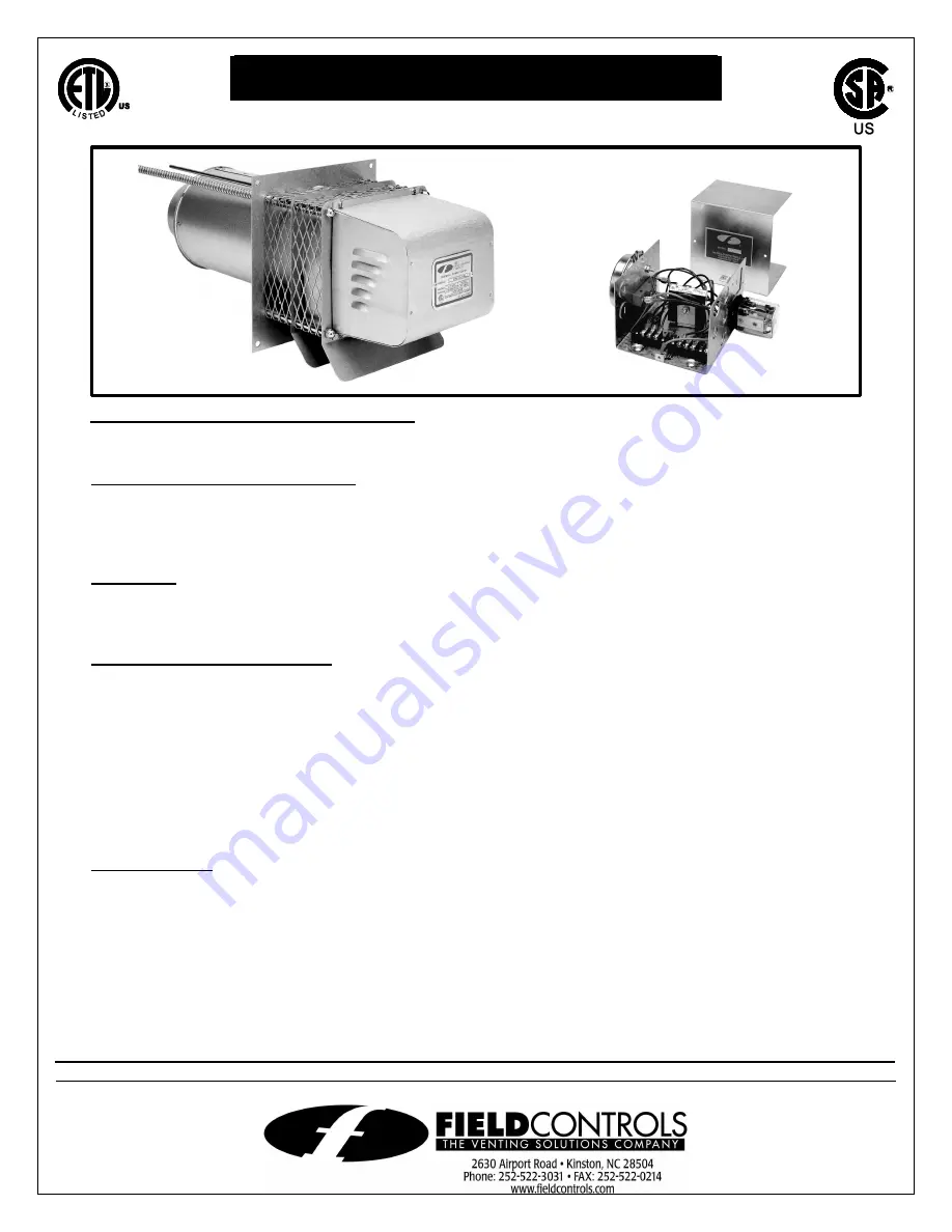
SIDEWALL POWER VENTER KIT  

Model: 

SWG II AGA Series 

*Patented 

TYPICAL VENTING SYSTEM COMPONENTS 

1 - SWG Series Power Venter 
1 - CK Series Control Kit 

OPTIONAL SYSTEM COMPONENTS 

SWG S

ERIES 

T

HROUGH

-W

ALL 

E

XTENSION 

K

IT

:

 For installation in wall thickness over 8 inches. Models PEK-4 

through PEK-8 are available. 

F

OR 

M

OST 

M

ULTIPLE 

H

EATING 

E

QUIPMENT 

S

YSTEMS

:


One CK Series Control Kit for each appliance. Except for 

a gas furnace and a water heater multiple venting system, use the CK-90 Series Control Kit. 

CONTENTS 

Installation Instructions ................................. 2 
Air Flow Adjustments .................................... 7 
General Installation Inspection ..................... 8 

Maintenance ................................... 9 
Replacement Parts ......................... 9 
System Information....................... 10 

GENERAL SYSTEM OPERATION 

Designed for operation with natural or LP gas appliances. 
1.  The thermostat (wall thermostat, or aquastat) calls for heat and energizes a relay which activates the 

power venter. After the venter motor has come up to speed, the pressure switch closes. This closes the 
circuit to the burner and allows the burner to operate. 

2.  For millivolt controlled water heaters, the gas valve pressure switch activates the power venter at the 

same time as the burner fires. 

3.  After the heating requirement has been satisfied, the thermostat circuit will open and de-activate the 

burner and power venter circuit. 

4.  For venting system equipped with a post purge device, the power venter operates for a period of time 

after the burner has shut off to purge remaining flue gases. 

CONTROL KITS: 

CK-41:

  For operation with gas-fired furnaces, boilers, unit heaters and water heaters operating with 24 VAC 

gas valve. For systems with factory-mounted spillage switches, use the CK-40 Control Kit. 

CK-43: 

For draft induced 24 VAC gas valve systems. Includes a 4" MG-1 draft control and electronic post 
purge. 

CK-81: 

For operation with 750 millivolt operated boilers, furnaces, water heaters, pool or spa heaters and 
gas-fired fireplaces when operating with remote mounted thermostat. Operated off a 24 VAC 
thermostat. For operation off of a 120 VAC thermostat or wall switch, use the CK-80. 

CK-90: 

For operation with a gas-fired furnace or boiler and a 30 millivolt water heater. 

CK-91: 

For gas fired draft induced 24 VAC gas valve systems and a 30 millivolt operated water heater. 
Includes a 4" MG-1 draft control and an electronic post purge. 

DO NOT DESTROY 

THESE INSTRUCTIONS MUST REMAIN WITH EQUIPMENT  


Summary of Contents for 46229000

Page 1: ...ivates the power venter at the same time as the burner fires 3 After the heating requirement has been satisfied the thermostat circuit will open and de activate the burner and power venter circuit 4 For venting system equipped with a post purge device the power venter operates for a period of time after the burner has shut off to purge remaining flue gases CONTROL KITS CK 41 For operation with gas...

Page 2: ...tained from combustible materials Class B Vent Pipe should be used for gas appliances and Class L Type Vent Pipe for oil appliances Refer to national or local codes for guidelines 5 Disconnect power supply before making wiring connections to prevent electrical shock and equipment damage 6 This equipment is designed to overcome minor negative pressure conditions To ensure extreme negative pressure ...

Page 3: ...zing based on appliance maximum input rate not actual firing rate Do not exceed maximum BTU HR input rating or maximum oil GPH input For multiple venting system applications add the input for each appliance Category I gas fired draft induced systems require an SWG 4 HD or larger Category III gas fired draft induced systems require an SWG 5 or larger PROCEDURE FOR CALCULATING TOTAL EQUIVALENT PIPE ...

Page 4: ... insure that the motor and blower wheel rotate freely DO NOT install if any damage is apparent Refer to unit sizing chart to check proper venting sizing 2 Location of the termination of the venting system should be installed in accordance with the National Fuel Gas Code A N S I Z223 1 and or manufacturer s recommendations which are applicable See requirements below or refer to installation locatio...

Page 5: ...ing should be cut so that the unit mounts directly on the wall board to provide a stable support If the siding is greater than 1 2 thick use a spacer plate or board behind the power venter mounting plate See Figure 4 NOTE If mounting the power venter through a combustible wall material and the flue gas temperature is above 400 F at the power venter inlet line the square hole with a piece of corros...

Page 6: ...The horizontal section of the vent pipe should have a slight upward slope from the appliance to the power venter For clearances to combustible materials multiple appliance venting and other installation requirements refer to the National Fuel Gas Code A N S I Z223 1 and or any applicable local codes or appliance manufacturer s installation instructions INSTALLATION USING SINGLE WALL VENT PIPE INST...

Page 7: ... stabilize flue gas temperatures check for negative draft or up draft at the heating appliance outlet or air flow into the draft hood Use a draft gauge velocity meter or match test procedure Adjust the adjustment damper closed to obtain the minimum air flow required to maintain draft Then increase air flow slightly 10 over minimum air flow rate to ensure proper venting For gas fired power burners ...

Page 8: ... Fuel Gas Code A N S I Z223 1 or any applicable local codes for guidance 3 Place in operation the appliance being inspected Follow the lighting instructions and adjust thermostat so appliance will operate continuously 4 Determine that the pilot or burner is operating properly and that the main burner ignition operates satisfactorily by interrupting and re establishing the electrical power of the a...

Page 9: ...er choke plate to insure it is secured in place Check the barometric draft control if installed to insure the gate swings freely 4 System Safety Devices With the heating system operating disconnect the pressure sensing tube from the pressure switch on the CK Kit This will stop the burner operation Re connecting the tube will relight the burner For 30 millivolt operating systems disconnect one lead...

Page 10: ...e circular cover plate with the holes in the motor mount bracket on the motor assembly See Figure 12 2 Slide the motor assembly onto the protruding threaded studs on the venter body with the exhaust chute pointing downward and replace the four nuts securely to the threaded studs See Figure 12 3 Reattach the flexible conduit and wires to the motor and secure the cover on the electrical box 4 Instal...

Page 11: ...Page 11 ...

Page 12: ...PN 46229000 Rev A 08 00 ...

Reviews: