background image

TRAX Apollyon Plus II User’s Manual

1-4

Battery Conservation

The Apollyon Plus II has a battery-saving feature that turns the display 
off if no keys have been pressed for 2 minutes. The Apollyon Plus II 
is still on and running, but the display has shut itself off to conserve 
power. When the Apollyon Plus II goes into this conservation mode, 
you need only hit any of the keys on the keypad for the display to come 
back up.

Similarly, the Apollyon Plus II has another feature that will turn itself 
off completely if no keys are pressed for 10 minutes (if there is no 
count in progress, of course). If this occurs, you can press the POWER 
key and the Apollyon Plus II will turn itself back on. The nice thing 
about this feature is that it will help preserve the Apollyon Plus II’s bat-
teries if the Apollyon Plus II is accidently left turned on.

Apollyon Plus II off at any time, regardless of which screen you are on, by 
pressing and holding the POWER key down for 5-6 seconds.

Now that we’re familiar with how to turn the Apollyon Plus II off and on, 
let’s restart it and start looking at some of the features. Press the POWER 
key again to restart the Apollyon Plus II and let it boot up to the Main 
Menu.

Menu Navigation

There are two keys on the keypad of the 
Apollyon Plus II that are used to navigate 
through the various screens and select op-
tions. The black TAB key is used for naviga-
tion, while the red DO key is used to select 
an option. In general, you press the TAB key until the option you want is 
flashing, and then press the DO key to select the option. If you move the 
highlight too far and overshoot the desired option, just keep pressing the 
TAB key until it is re-selected. Let’s see how this works.

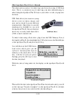
The Main Menu shows several op-
tions on the top line – Count, USB 
and Utils. Notice that 

Count

 is 

flashing. This means that it is the 
currently active option. Now, press 
the TAB key once and notice that 

Press to move 

highlight

Press to select 

option


COUNT     USB   UTILS  :0


Bat:3.6v


:0

  Count:00             7104K  :0
  15:21:58           02/13/18  :0

Main Menu

Summary of Contents for TRAX Apollyon Plus II

Page 1: ...i Automatic Traffic Data Recorder User s Manual JAMAR Technologies Inc TRAX Apollyon Plus II ...

Page 2: ...perly installed road tube or damage caused by improper installation in disregard of the instructions furnished by us This warranty does not extend to products which have been repaired or altered outside our factory or authorized service agent InnoeventshallJAMARTechnologies Inc beliableforanydamagesarisingfrom the use of this product including damages arising from the loss of information This warr...

Page 3: ...dditional information For the latest support information on the TRAX Apollyon Plus II please visit our web site at http www jamartech com traxapollyonplusii html Support is also available by e mail at support jamartech com Support is also available by phone at 1 215 361 2244 Monday Friday 8 00 AM to 5 00 PM Eastern time Volume 1 1 August 2018 ...

Page 4: ...Apollyon Plus II Powered 2 2 Using the Keypad 2 2 Start up Screens 2 3 Main Menu 2 4 Utilities Menu 2 5 Tube Spacing 2 5 Data Interval 2 6 Dead Time 2 6 Time Date 2 7 Clear 2 7 System 2 7 Tests 2 9 Count Menu 2 11 Tubes 2 11 Basic 2 11 Volume Only 2 11 Tube Layout Selection 2 12 Site Code 2 12 Count Start up Menu 2 14 GPS 2 14 STAT 2 15 Start 2 15 Basic Data Status Screens 2 15 Volume Only Status ...

Page 5: ...ation Equipment 3 4 Step 5 Install the Road Tubes 3 4 Step 6 Check for Accuracy 3 5 Chapter 4 Road Tube Layouts 4 1 Layouts for the TRAX Apollyon Plus II 4 2 Layout L1 4 3 Layout L2 4 4 Layout L3 4 5 Layout L4 4 6 Layout L5 4 7 Layout L6 4 8 Chapter 5 Troubleshooting FAQ 5 1 Appendix A 1 Installing USB Drivers A 2 Low Speed Data Collection A 7 FHWA Type F Classification Scheme A 9 Memory Table A 1...

Page 6: ...ally running in the lanes Once the tubes are down mastic those running areas so as to avoid bounce 2 Turn the TRAX Apollyon Plus II ON by pressing the POWER button Make sure the Main Power toggle is set to ON 3 TAB to Utils and press the DO key once 4 Check the tube spacing currently set for the study Sp The spacing should be set to 1 0 ft To change the Spacing press DO with Sp flashing Otherwise ...

Page 7: ...1 1 Chapter 1 Introduction to the TRAX Apollyon Plus II Chapter 1 Introduction to the TRAX Apollyon Plus II ...

Page 8: ...he data for the study At any convenient time you can transfer the data to the TRAXPro software on your computer using the USB Download Port Note that you can also transfer the data to a USB flash drive using the USB Memory Port Once on the flash drive the data can be easily transferred to TRAXPro on your computer Once the data is in the TRAXPro software reports for volume class speed and gap can b...

Page 9: ...face plate which contains a display for showing infor mation and keys for entering data Note the Main Power toggle switch located at the top middle of the Apollyon Plus II As the name sug gests this switch controls the main battery connection to the Apollyon Plus II This toggle should always be left set to ON except in cases where the unit is no longer responding to the POWER key described below a...

Page 10: ...y pressing and holding the POWER key down for 5 6 seconds Now that we re familiar with how to turn the Apollyon Plus II off and on let s restart it and start looking at some of the features Press the POWER key again to restart the Apollyon Plus II and let it boot up to the Main Menu Menu Navigation There are two keys on the keypad of the Apollyon Plus II that are used to navigate through the vario...

Page 11: ...e op tions that can be selected are Tube Spacing Sp Interval Length Int Dead Time DT Time Date Clear System and Tests To start let s take a look at the first option setting the Tube Spacing High light the Sp option then press DO Setting the Tube Spacing When collecting data that will be processed for speed or classifica tion you have to use a tube layout with at least two road tubes set at a fixed...

Page 12: ...e not the data you produce will be inaccurate Highlight Time Date then press the DO key To change a value in this screen you press the TAB key to highlight the field you want to change You then press the Change keys numbers 3 and 6 to either scroll up or down through the values Let s give this a try With HR flashing press the 3 key several times and notice that the hour value increases up Now pres...

Page 13: ...t be When you select the Clear option the Apollyon Plus II does not immediately clear the memory Instead it brings up the first of two confirmation screen that you must go through before the memory is actually cleared This is designed to prevent you from accidentally clear ing the memory To clear the memory you must confirm that that is what you want to do on both confirmation screens How often yo...

Page 14: ...nt Highlight Exit on the Utilites menu the press DO to return to the Main Menu Frequently Asked Questions Regarding Data Memory There are a few common questions people ask related to the memory of the Apollyon Plus II Q If I download the data from the Apollyon Plus II to the computer does that remove the data from the Apollyon Plus II A No You can download the same data as many times as you like a...

Page 15: ...peed classification gap all from the same original file With Volume Only data as the name implies you can only get volume information This format also does not time stamp every axle but rather sorts and stores the volume data into specific interval times In general we recommend that you use the Basic format whenever you can There are several reasons for this the most important of which is that if ...

Page 16: ...lecting accurate bicycle classification data is the L5 or L6 layout If you need to produce reports for speed or classification data the most commonly used layout is L6 This is designed for standard two lane roads with traffic traveling in opposite directions Another commonly used lay out is L5 which is designed for one lane of traffic or possibly two if each lane is going in the same direction Not...

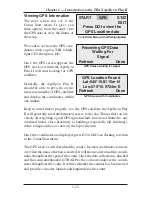
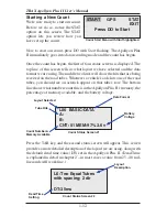
Page 17: ...lose proximity to buildings especially tall buildings dense foliage and ice or snow on the top of the unit Once the coordinates are displayed press DO with Done flashing to return to the Count Start menu The GPS receiver will download the count s location coordinates to mem ory when the data collection is started It will then re download the coordi nates throughout the span of the count Once the d...

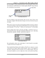
Page 18: ...e road tubes you should see an asterisk appear on that tube s row The bottom line shows what number count this is in the Apollyon Plus II s memory the percentage of memory available and the battery voltage Press the TAB key and the second status screen will appear This screen provides a more detailed description of the layout we are using along with the default dead time value DT set in the Apolly...

Page 19: ...r for Fair G for Good and for Excellent In the example shown below the pulse strength is excellent for the A C and D tubes However the pulse strength for the B tube is poor indicating that the tube should be checked and possibly replaced By checking this screen you can determine if a tube should be reinstalled or replaced before leaving the site Note that the Main Menu of the Apollyon Plus II also...

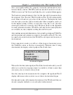
Page 20: ...ile in memory Go ahead and do that now to end the count we started Once the unit is turned off press the POWER key to start it back up again Downloading Your Data Once you have collected data and stored it in memory the next step is to download it The data can be downloaded either directly to a computer using the USB Download Port or to a USB Flash Drive through the USB Memory Port We ll cover bot...

Page 21: ...king the selection easier After making any needed adjustments click on the Begin button inTRAXPro and the program will attempt to connect to the Apollyon Plus II The traf fic signal icons at the bottom of the TRAXPro screen provide the status of the download If the connection is made you will see a blue progress bar moving across the TRAXPro screen as the data is transferred While the data is bein...

Page 22: ...o the USB Memory Port of the Apollyon Plus II then highlight the USB selection on the Main Menu of the Apollyon Plus II and press the DO key You will then see the USB Down load screen which gives you the option to download the data in memory to the flash drive To do this with the Download option flashing press the DO key to start the data download While the data is being retrieved the display on t...

Page 23: ...XPro and select Acquire USB Flash Drive Congratulations Now that you have completed this tutorial you should have a good working knowledge of how the Apollyon Plus II operates The next chapter covers all the options and features of the Apollyon Plus II in detail both those we touched on in this tutorial and additional ones We commend you on your choice of the TRAX Apollyon Plus II for your data co...

Page 24: ...TRAX Apollyon Plus II User s Manual 1 18 ...

Page 25: ...2 1 Operational Features of the TRAX Apollyon Plus II Chapter 2 Chapter 2 Operational Features of the TRAX Apollyon Plus II ...

Page 26: ...Apollyon Plus II off press and hold down the button for five seconds Note that the Apollyon Plus II also has a Main Pow er toggle switch which is located at the top middle of the Apollyon Plus II As the name suggests this switch controls the main battery connection to the Apollyon Plus II This toggle should always be left set to ON except in cases where the unit is no longer responding to the POWE...

Page 27: ...pad After you power on the Apollyon Plus II the sign on screen is displayed This shows the version number of the firmware in the Apollyon Plus II on the bottom line The firmware is the internal program that the Apollyon Plus II uses to operate If you ever encounter a problem with your unit and request support for it you may be asked for this version number After a few seconds the screen clears and...

Page 28: ...y of the Apollyon Plus II UTILS Perform miscellaneous operations that include the option to clear the memory of the Apollyon Plus II set the time date perform diagnostic tests and program a variety of default settings Note that the four numbers on the far right side of the display are related to the Apollyon Plus II s road tube testing feature Any time you have road tubes connected to the Apollyon...

Page 29: ...ssed for speed or classification you have to use a tube layout with at least two road tubes set at a fixed distance apart L5 or L6 It is by knowing what this fixed distance is that speed and classification can be determined The currently set tube spacing is shown To change this use the TAB button to select Sp and press DO The screen shown here will then be displayed The typical value used for this...

Page 30: ...ore it will accept another one This helps the Apol lyon Plus II to eliminate extraneous pulses caused by an initial pulse reverberating in the road tube The currently set DT is shown To change this use the TAB but ton to select DT and press DO The screen shown here will then be displayed Typically the DT value is set for 35 milliseconds which will give good results on most traffic travelling at sp...

Page 31: ...ows you to clear the memory of all data You are given two chances to change your mind before the data is permanently removed from the nonvolatile memory System This option allows you to pro gram some of the system set tings of the TRAX Apollyon Plus II To access these settings press the TAB key until System is flashing then press the DO key The screen shown here is then displayed Date This selecti...

Page 32: ...r split the file and to run in continuous mode This is the most commonly used option The Daily option tells theApollyon Plus II to store the data in daily files splitting it at 12 AM while the Weekly option tells it to split the study on a weekly basis splitting it at 12 AM Sunday These options are normally only used if the Apollyon Plus II is set up at a permanent location and data is being retri...

Page 33: ...test will check all memory locations in the unit s 8 MB memory To perform the test press DO while Memory is flash ing and the TRAXApollyon Plus II automatically starts testing the memory Note that the memory must be cleared of any count data before the test can be performed Display Test The Display test allows you to view all segments of the liquid crystal display to be sure the display has not be...

Page 34: ...ever the pulse strength for the B tube is poor indicating that the tube should be checked and possibly replaced Note that the Main Menu of the TRAX also contains a version of this tube test feature which assigns numeric values to the strength of the pulses ranging from 0 for no pulse to 9 for strongest pulse Refer to page 2 4 for more details Should you see a channel that is reading weak you can s...

Page 35: ...note In general we recommend that you use the Basic format whenever you can There are several reasons for this the most important of which is that if something goes wrong with one of your counts it is much easier to determine why and potentially fix the problem without having to re do the count if the data is collected in the Basic format Selecting this type of count will take you into the tube la...

Page 36: ...outs for more detailed descriptions of the layouts Listed below are the types of layouts that can be used depending on the data collection mode selected Volume Only 1 or 2 Road Tubes L1 L2 L3 L4 Basic 1 or 2 Road Tubes L1 L2 L3 L4 L5 L6 Note that only the L5 and L6 layouts can produce data that can be analyzed for speed and class information Press DO when the layout you want to use is flashing You...

Page 37: ...use numbers lower case letters upper case letters and or symbols Use of an alpha numeric site code allows you to include street names or other text as part of your identification information When you first enter the Alpha numeric site code screen the first field is flash ing along with the OK selection To enter a value press the TAB key until the field for numbers up per case letters lower case le...

Page 38: ...ess to the sky Things that can ad versely affect getting a good GPS signal include but are not limited to any overhead metal close proximity to buildings especially tall buildings dense foliage and ice or snow on the top of the unit Once the coordinates are displayed press DO with Done flashing to return to the Count Start menu Note that the coordinates displayed on the GPS screen may not be the e...

Page 39: ...on Plus II is collecting data Press the TAB key to page though the available status screens The following are examples of the types of screens that are available for review depending on the study you have programmed Basic Data Status Screens The top line of this screen gives the layout that has been selected L6 and the type of study being done Basic The next two lines represent the tubes that data...

Page 40: ...e study is being conducted By using the screen you can check to see if any road tubes are starting to fail while you are still collecting data Volume Only Status Screens The top line of this screen tells you the way in which the data is being collected CHNL CNTS or Channel Counts and the current interval number Int 0001 The next two lines give you the total per channel for the current interval The...

Page 41: ...e of memory available MEM 99 and the battery voltage 3 6v The top two lines of this screen tell you the layout selected and how the tubes should be arranged for this study The fourth line tells you what length of interval is being used for the study Intv 15min The top line of this screen gives the date and time as they are set in the TRAX Apollyon Plus II The next three lines provide infor mation ...

Page 42: ...The Apollyon Plus II will turn off and the count will be stored in its internal memory Additional studies can then be conducted with the unit The TRAX Apollyon Plus II can hold up to 150 different studies in its memory You can also end the count through the options accessed by hitting the DO key while a study is in progress The New option will end the cur rent count and immediately begin a new one...

Page 43: ...he Count Status screen visible to download data If the Main Menu is visible the download will transfer all data currently stored in memory If the Count Status screen is visible the download will transfer all counts stored in memory but not the count currently being done If you have a count in progress that you would like to download you must end the count using one of the options discussed on page...

Page 44: ...reen for assigning a name to your file or if there is more than one count a list of counts to choose from Once the data has been transferred to the computer the Apollyon Plus II display will return to the screen it was on before the download began Downloaded counts will remain in the memory of the TRAX until they are cleared using the method described on page 2 7 USB Flash Drive Download The other...

Page 45: ...ata download While the data is being retrieved the display on the Apollyon Plus II will show When all of the data in theApollyon Plus II has been downloaded you will see the message Transfer Complete on the Apollyon Plus II It will then return to the screen it was on before the download began Note We recommend that you do not clear the memory of the Apollyon Plus II until you have successfully bro...

Page 46: ...TRAX Apollyon Plus II User s Manual 2 22 ...

Page 47: ...3 1 Chapter 3 Road Tube Installation Chapter 3 Road Tube Installation ...

Page 48: ...use Installing Road Tubes Proper road tube installation is very important for collecting accurate data with your TRAX Apollyon Plus II The road tube and the TRAX Apollyon Plus II s air switches comprise the sensing device for the unit As with all receivers the sensor has to be functioning properly to record reliable in formation With this in mind examine your installations carefully and be absolut...

Page 49: ...the best results based on extensive testing L1 L3 L4 L5 L6 Long tube setups To encompass all types of vehicles and speeds a tube length of 40 to 60 feet for mini tube These lengths should satisfy all requirements for normal street road highway and interstate traffic patterns L2 Short tube long tube To ensure the pulses from the road tubes arrive at the counter in the proper order the tube length m...

Page 50: ...ane are not coming in contact with the short tube IMPORTANT For accurate bicycle data you must use mini tube with a 3 16 1875 inside diameter and 3 8 375 outside diameter Do not use large 9 16 OD tubing with a small ID because bicycles are too light to make the pulse needed with these tubes Since mini tube is smaller and lighter than standard round tube less hard ware is required to install the tu...

Page 51: ... data is being recorded as programmed Upon completion of your data collection remove the tubes clamps nails and anything else that may be of danger to the motorists The mastic may be hard to remove in some instances especially in hotter weather In those cases it may be left on the highway and eventually it will blend into the asphalt from the flow of traffic Chapter 3 Road Tube Installation Mastic...

Page 52: ...TRAX Apollyon Plus II User s Manual 3 6 ...

Page 53: ...4 1 Chapter 4 Road Tube Layouts Chapter 4 Road Tube Layouts ...

Page 54: ...from the end of the road to the TRAX must be the same for all tubes In all short tube long tube layouts the vehicle must strike the short tube first To collect class or speed data a minimum of one foot of tube spacing is required to achieve accurate results For counts done in the Volume Only mode the TRAX Apollyon Plus II will either do a straight axle count or use the divide by two technique in w...

Page 55: ...The TRAX has been programmed to use the divide by two technique As a passenger car passes over the A the unit records one count As a four axle truck passes over the A tube the unit records two counts A B TRAX Layout L1 Sensors Used 2 Road Tubes Spacing None Count Formats Basic Volume Only Data Volume Gap Channels 2 Channels A B Chapter 4 Road Tube Layouts 50 feet 50 feet 26 ft 24 ft ...

Page 56: ...ither direction EXAMPLE The TRAX has been programmed to use the divide by two technique As a car approaches the tubes in the inner lane and both front and rear axles pass over the A and the B tube the unit records a one in theA channel but ignores the hit on the B channel since it occurred immediately after the A hit As a second car approaches the tubes in the outer lane and both front and rear ax...

Page 57: ...uthbound approaching the tubes As the front and rear axles strike the A tube a one is registered in the A channel The front and rear axles then strike the B tube but these hits are ignored since the A tube has just been hit Conversely a car traveling northbound will strike the B tube first recording it in the B channel and then have its hits on the A tube ignored B TRAX A 4 Inch Spacing Layout L3 ...

Page 58: ...he TRAX can do either a straight axle count or use the divide by two technique This layout can be used with single direction or bidirectional traffic however there is no lane separation TRAX A Layout L4 Sensors Used 1 Road Tube Spacing None Count Formats Basic Volume Only Data Volume Gap Channels 1 Channel A 50 feet 26 ft 24 ft ...

Page 59: ...oth the A and B tubes the TRAX records the class and speed or time stamps of the vehicle B A North TRAX Layout L5 Sensors Used 2 Road Tubes Spacing One Foot for Road Tubes Count Formats Basic Data Class Speed Gap Volume Directions 1 Direction A to B Spacing 1 foot Chapter 4 Road Tube Layouts 50 feet 26 ft 24 ft Note that in some cases you can extend the tubes across two lanes of traffic if you hav...

Page 60: ...nel A and channel B record dependent on each other The tubes should be spaced one foot apart and be of equal length EXAMPLE A car is traveling southbound approaching the tubes As the vehicle passes over both the A tube then the B tube the TRAX records the class and speed or time stamps of the vehicle in the first direction A car traveling northbound passing of the B tube then the A tube gets recor...

Page 61: ...Formats Basic Volume Only Data Volume Gap Channels 4 Channels A B C D This layout is the same as the L1 layout but with four tubes over four sepa rate lanes rather than two tubes over two lanes Refer to the L1 description for more information A B C D TRAX 26 ft 24 ft 50 feet 50 feet 26 ft 24 ft ...

Page 62: ...sic Volume Only Data Volume Gap Channels 4 Channels A B A C D C This layout is the same as the L2 layout but with four tubes over four lanes rather than two tubes over two lanes Refer to the L2 description for more information The tubes should be spaced two feet apart 2 foot spacing between tubes 26 ft D C 12 ft 12 ft 24 ft 24 ft B A TRAX 26 ft ...

Page 63: ... to A C to D D to C This layout is the same as the L3 layout but with four tubes over four lanes rather than two tubes over two lanes Refer to the L3 description for more information The tubes should be spaced four and a half inches apart D C 4 inch spacing between tubes B A TRAX 24 ft 24 ft Traditional Road Tubes EZ Belt D C B A 25 ft Mini 25 ft Mini 24 ft 24 ft TRAX 26 ft 26 ft ...

Page 64: ... C B A 38 ft 38 ft 12 ft 12 ft TRAX Layout L10 Layout Type EZ Belt or Traditional Road Tubes Sensors Used 4 Road Tubes Spacing Two Feet Count Formats Basic Data Class Speed Gap Volume Directions 2 Directions A to B C to D 2 foot spacing between tubes Traditional Road Tubes D C B A 26 ft 24 ft TRAX 2 foot spacing between tubes OR 24 ft 26 ft Note that counting two lanes with one set of tubes A and ...

Page 65: ...Mini 13 ft 13 ft TRAX Note Standard 26 belt can be cut in half OR D C B A 26 ft 26 ft 25 ft Mini 25 ft Mini TRAX Note that counting two lanes with one set of tubes A and B or C and D will result in a decrease in accuracy as volumes increase ...

Page 66: ... The A tube should be spaced six inches from the B tube and the C tube should be spaced six inches from the D tube Remember vehicles must always strike the short tube first B A 24 ft 26 ft 12 ft D C 6 inch spacing from A to B and from C to D Layout L11 Layout Type Traditional Road Tubes Sensors Used 4 Road Tubes Spacing Two Feet A to C and B to D Six Inches A to B C to D Count Formats Basic Data C...

Page 67: ...ut for bidirectional traffic Refer to the L11 layout for further information The A and C tubes should be spaced two feet apart as should the B and D tubes The A tube should be spaced six inches from the B tube and the C tube should be spaced six inches from the D tube Remember vehicles must always strike the half tube first B A 24 ft 26 ft 12 ft D C 6 inch spacing from A to B and from C to D 2 foo...

Page 68: ...e as the L2 layout but with the addition of a tube for a third channel Refer to the L2 layout for further information The tubes should be spaced two feet apart For improved accuracy with this type of data collection we recommend that the L7 layout be used with the Road Ramp system to isolate each lane Visit our web site at www jamartech com for more information 26 ft B TRAX A 12 ft 2 foot spacing ...

Page 69: ...addition of two tubes for two additional channels Refer to the L2 layout for further information The tubes should be spaced two feet apart For improved accuracy with this type of data collection we recommend that the L7 layout be used with the Road Ramp system to isolate each lane Visit our web site at www jamartech com for more information 26 ft B TRAX A 48 ft 12 ft 2 foot spacing between tubes C...

Page 70: ...TRAX Apollyon Plus II User s Manual 4 18 ...

Page 71: ...5 1 Chapter 5 Troubleshooting FAQ Chapter 5 Troubleshooting FAQ ...

Page 72: ...splay automatically goes out when no keys on the keypad have been pressed for two minutes To bring the display back up hit any key If the TRAX is left inactive for 10 minutes or more and it is not in data collection mode it will turn itself off completely In this case press the POWER key to restart the TRAX When the Apollyon Plus II is turned on the display reads Improper Shutdown What s wrong If ...

Page 73: ...s available when in data collection mode including the tube test screen To view these screens press the TAB key The data I m getting is not accurate What went wrong In most cases issues with bad data are related to the road tubes and how they were installed Check the tube layout used in the field and the condition of the tubes themselves Make sure the tubes were set with the proper length spacing ...

Page 74: ...yon Plus II shows only black boxes on the display and won t turn off when I press the POWER button In this case the Apollyon Plus II may need a hard reset To do this switch the Main Power toggle to OFF then back to ON Once that has been done try pressing the POWER button again Additional support information can also be found on our web site at www jamartech com If you are unable to find a solution...

Page 75: ...A 1 Appendix Appendix ...

Page 76: ...er and then to the USB port of the TRAX Next turn the TRAX on TheWindows Found New Hardware message will pop up referencing USB Serial Converter then the Found New Hardware Wizard will appear One of the features of Windows 7 8 is to use your Internet connection to search the Windows Update web site for any available drivers for USB devices you connect to your computer like the TRAX Apollyon Plus I...

Page 77: ...rough the Windows Update web site as this is the easiest method for load ing the drivers However if you are not able to use theWindows Update web site the drivers are also available on the Downloads section of the JAMAR web site If you are downloading the drivers from the JAMAR web site be sure to follow the directions listed there Once you are ready to pro ceed click Next The Wiz ard will then st...

Page 78: ...u ll see a screen like the one shown to the right Click Finish and you ll complete installing this driver but there s still one more to go Once you click Finish the Windows Found New Hardware message will pop up again referencing a USB Serial Port and the Found New Hardware Wizard will reappear Don t be alarmed this is what s supposed to happen There is a second driver that needs to be installed t...

Page 79: ...ted a virtual comm port on your computer and assigned this port a number You will need to select this comm port number in the JAMAR software when you go to download your TRAX The software makes this easier to do by only listing the comm ports that are available in the download screen However if you want to check to see what port number the virtual comm port has been assigned you can do so through ...

Page 80: ...he My Computer icon then select Properties In the System Properties window click on the Hardware Tab then click the Device Manager button Click the plus sign next to Ports and you should see a list similar to the one shown below showing the port number that your computer has assigned ...

Page 81: ...led as it hits the tubes The Dead Time setting is used to keep these extra hits from showing up as additional volume in the data This setting allows you to set a specific time in the TRAX when it will not accept a new pulse from the road tube after it has just received a pulse At normal traffic speeds the time from one tire of an axle hitting the tube to when the other tire from an axle hits the t...

Page 82: ... result you may choose to extend the road tube only as far as is necessary to be hit by one side of the vehicle The above rules may be varied slightly since each tube installation for low speed traffic counting is unique The tube length and DT may be adjusted to fit your specific parameters Once you have decided on your settings monitor incoming data to ensure accuracy With low speed data collecti...

Page 83: ...es which are pulling recreational or other light trailers are included Class 4 Buses This class includes all vehicles manu factured as traditional passenger carrying buses with two axles and six tires or three or more axles This includes only traditional buses including school and transit buses functioning as passenger carrying vehicles All two axle four tire minibuses should be classified as Clas...

Page 84: ...icles with five or less axles consisting of three or more units in which the pulling unit is a tractor or single unit truck Class 12 Six Axle Multi Trailer Trucks This class includes all six axle vehicles consisting of three or more units in which the pulling unit is a tractor or single unit truck Class 13 Seven or More Axle Multi Trailer Trucks This class includes all vehicles with seven or more ...

Page 85: ...l by interval basis Each one of these intervals can be a maximum of 34 bytes in size which equals approximately 30 intervals per kilobyte or 480 000 intervals for the entire memory The table below lists the amount of continuous data that can be recorded with a given in terval time Interval Length Used Amount of Continuous Data 1 Minute Intervals Approximately 6 months 5 Minute Intervals Approximat...

Page 86: ...00 bps Memory 8 MB Internal Memory Clock Always active real time clock Data Collection Formats Volume Time stamped raw data Inputs Two road tubes Temperature Range Minus 40F 40C to 165F 74C Date Format USA MM DD YY or World DD MM YY Recording Intervals 1 5 10 15 30 60 minutes for Volume Only Units English feet or Metric meters Display Wide Temperature 4 line by 20 character LCD display Output Bina...

Page 87: ...ted before it leaves our facility However just like other complex electronic devices problems can occur We always suggest that users verify the continuing accuracy of any device they use Verification against manual counts or with a JAMAR Traffic Counter Tes ter should be performed on an annual basis as required by the FHWA to assure proper operations and results Should you detect any problems with...

Page 88: ...TRAX Apollyon Plus II User s Manual A 14 ...

Reviews: